
Please select the appropriate symptom from the list below:
Both HTC Vive Headsets show white screen during gameplay
ONE HTC Vive Headset is showing white screen during gameplay
Player 2 Not Crediting
No Motion at all from Motion Base
Motion from only ONE actuator on Motion Base
Game volume too low
Safety sensor showing blocked
PC will not power up or will not stay on
Other
Virtual Rabbids:
The Big Ride
Troubleshooting
Guide
SYMPTOM: ONE HEADSET HAS WHITE/GREY SCREEN DURING GAMEPLAY
STEP 1: Reseating the I/O connections on the headset
• Power off the game.
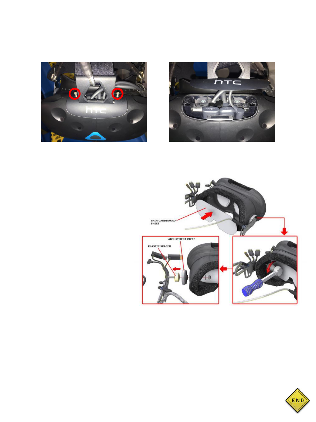
• Remove the 2 screws securing the cover.
• Remove the HDMI, USB and Power connections and firmly push them back into place.
• Replace the I/O cover and screws.
• Power the game back on.
• Test (If you are still seeing white screen continue to step 2).
STEP 2: Swapping Headsets to determine fault
• Once again, remove the I/O cover
and disconnect the HDMI, USB and
power.
• Before working on the headset it is
recommended to place a thin
cardboard sheet inside to protect the
lenses.
• Remove the 2 nuts and washers
from the inside and pull out the
security brackets. The headset
should be free from all tethers at this
point.
• Do this for the other headset and
swap positions.
• If the problem stays with the
position and does not follow the
headset, the 3-in-1 cable is faulty.
This is the end of this section. Click the button on the right to return to the main menu.
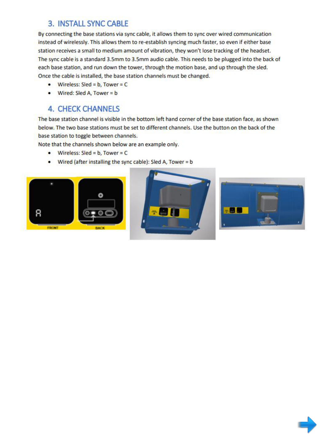
SYMPTOMS:
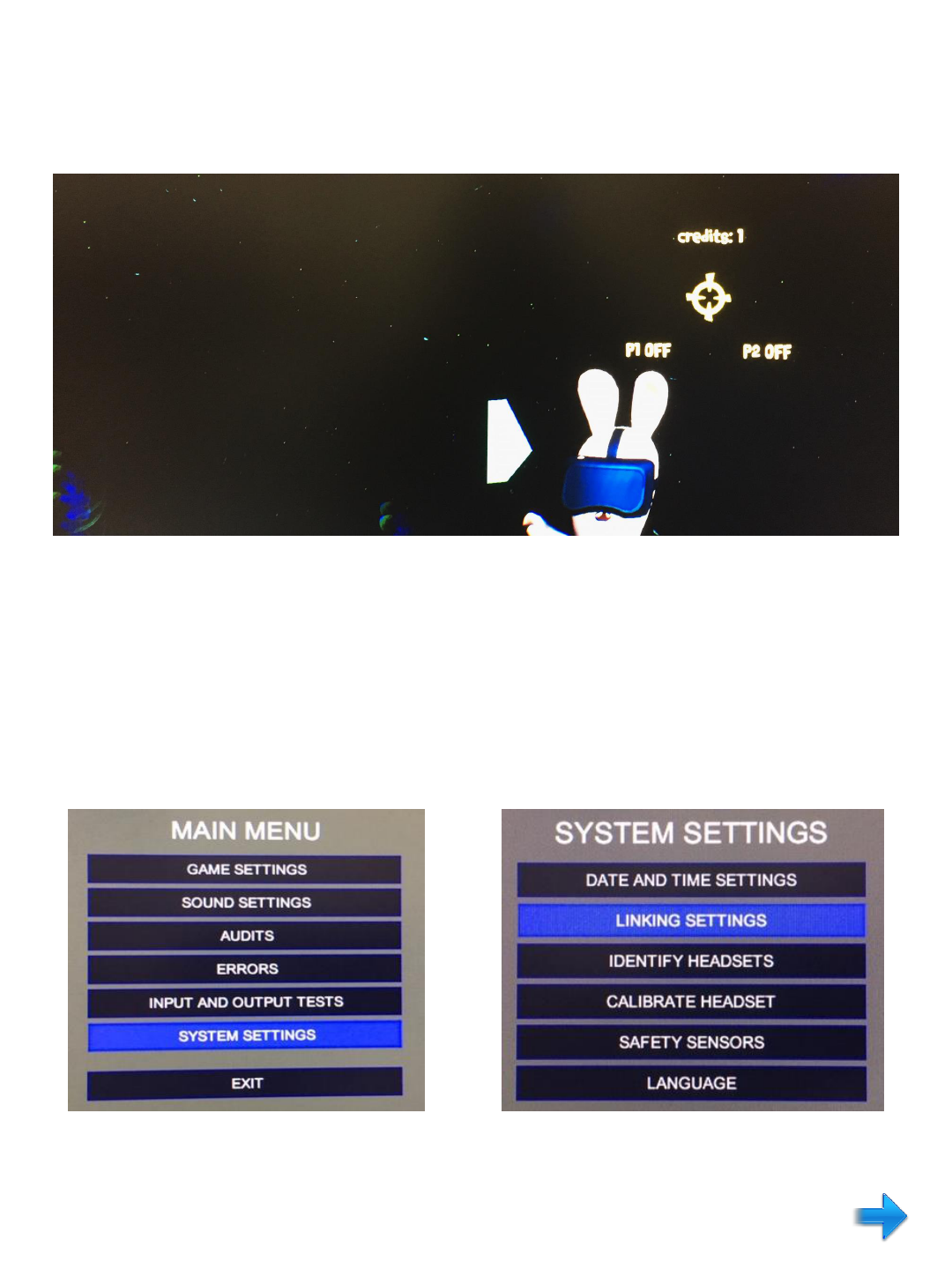
• P2 does not show credits while P1 plays as normal
• Top monitor display shows P2 and/or P1 labeled “OFF” instead of “WAITING” after coin up
If these issues are present, it most likely means the PCs are not communicating. Follow the
steps below to resolve.
STEP 1: Determine the PC address for PC1 (Refreshing Address)
• Insert the keyboard dongle into PC1 and turn on the keyboard.
• Press the letter “O” on the keyboard to enter the operator menu. You should then see this
screen below.
• Select “System Settings” then select “Linking Settings”

• The Player ID should show PLAYER_1. Even if the
Player ID is correct, toggle the Player ID to
PLAYER_2, then back to PLAYER_1. This will
“refresh” the Player ID and will save further steps
later.
• Exit the operator menu by pressing the letter “O”
on the keyboard.
STEP 2: Determine the PC address for PC2 (Refresh Address)
• Insert the keyboard dongle into PC2 and power down PC2 only using the power button located
on the front of the PC. Wait 60 seconds before powering back on.
• Change the HDMI switch to show PC2 image on the top monitor.
• Once the PC has booted up, enter the operator menu using the keyboard.
• Again, toggle the Player ID to PLAYER_1 and then back to PLAYER_2.
• Exit the operator menu.
• Change the HDMI switch back to PC1.
• Perform a power cycle on the entire game. Be sure to wait at least 60 seconds after everything
boots down before turning power back on.
STEP 3: Once the ride has booted up, test by crediting both sides. If the problem is not resolved,
continue to step 4.
STEP 4: Replace the cat5e cable that is linking both PCs. This will be the only Cat5e coming from
either PC. Once installed, power cycle the entire game and test. If the same results are seen,
proceed to step 5.
STEP 5: Perform a system image on both PCs (Re-install Software)
• Locate the recovery USB flash drive that came inside the Virtual Rabbid’s support kit.
• Follow the instructions in the manual on how to install.
This is the end of this section. Click the button on the right to return to the main menu.
D-BOX TROUBLESHOOTING GUIDE
Overview of Components
SYMPTOM: NO MOTION AT ALL
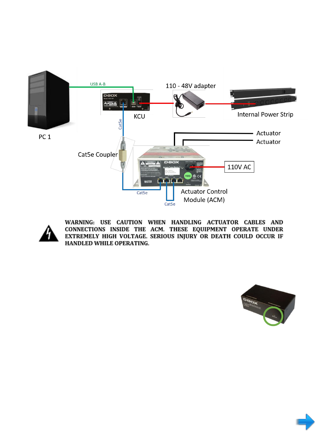
STEP 1: Open access door at the rear of the tower (bottom door), and locate the D-Box Motion
Controller KCU (black box on right above PC2).
STEP 2: Note the color of the indicator light on the box. Color codes are
below:
• No light – KCU is not receiving 48v > Check power plug in rear of KCU, check plug at 48V
adapter located below the PCs on the floor of the tower, check plug located on power strips
above the PCs.
• Red light – Not receiving signal from PC > check USB connection to KCU from PC1.
• Orange light – KCU is trying to obtain a signal (will usually see this when the KCU is booting
up)
• Green light – KCU is working properly (If you have a green light and there is no motion, follow
to Step 3).
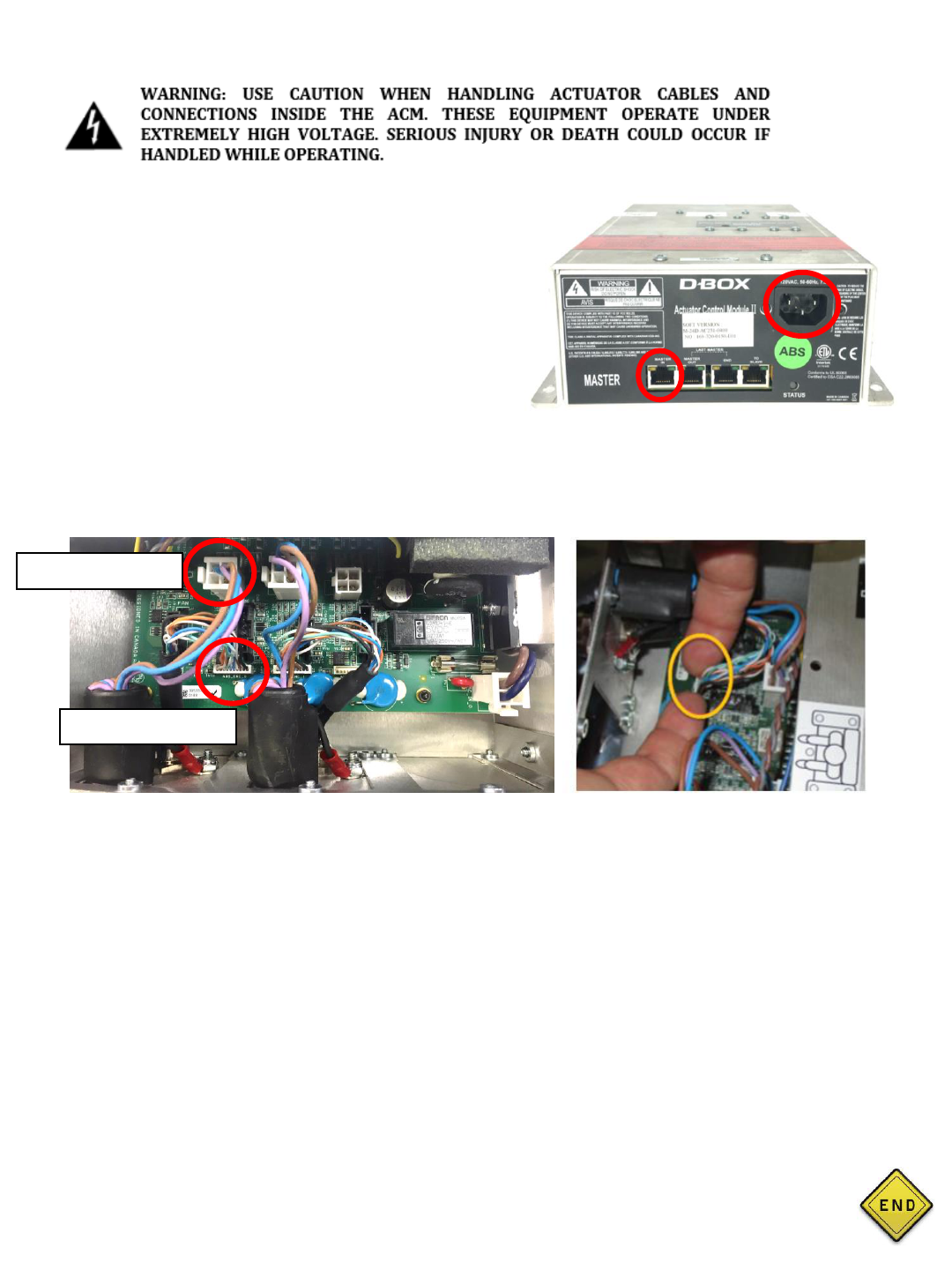
STEP 5: Checking the Actuator Control Module (ACM)
• Remove the skirt under player 2 seat
• Ensure the Cat5e cable, Jumper Cat5e cable and power are all firmly connected to the ACM
correctly.
• Check the lights
No lights – ACM has no power and no data.
Status light only – ACM has power but no data (most likely a bad cat5 cable or
coupler if all of the above steps have been followed).
Cat5 port lights only and no Status light – ACM does not have 110V (check power
cord to the ACM to ensure 110V is provided, check power connection to tower,
check power strip inside cabinet).
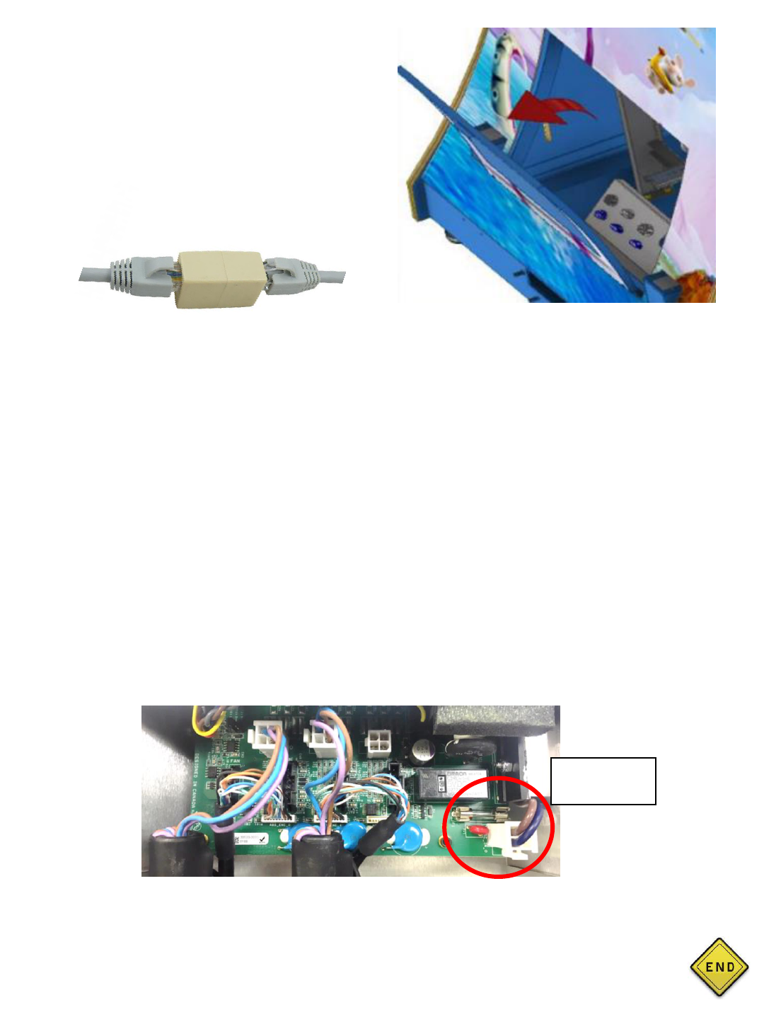
STEP 6: Opening the ACM to check the fuse and power connector
• Power off the game.
• Unplug power and cat5e from the ACM.
• Remove the 4 nuts securing the ACM to the motion base floor to allow for better access.
• Open only the area labeled “Access Cover” (Opening the entire top of the ACM will cause
damage to the components and void the warranty).
• Check the 8 amp fuse and reseat the power connector.
• If the fuse is good, reinstall the ACM and test. Contact your distributor if the problem persists.
Note the serial number on the ACM, you will need this for the D-Box warranty process.
Step 3: Check the Cat5e cable is securely plugged
into the rear of the KCU.
Step 4: Check that both Cat5e ends are connected
where the tower connects to the motion base
(open the lower front tower access door to check).
Firmly push both Cat5e terminals into the coupler
simultaneously. If there is motion, bypass this
coupler by using the Cat5e from the KCU to the
ACM.
This is the end of this section. Click the button on the right to return to the main menu.
Fuse & Power
Connector
SYMPTOM: ONE ACTUATOR NOT MOVING
STEP 1: Opening the ACM
• Power off the game.
• Remove the skirt under Player 2 seat.
• Unplug power and cat5e from the ACM.
STEP 2: Swapping the actuator connectors
• Determine the connectors for the working actuator.
• Very carefully, swap both connectors for both actuators.
• CAUTION: the encoder connector is fragile. Handle the connector with care. Do not
disconnect the connector by pulling on the wires. Use your index nails to extract the
connector as shown above in image 2.
• Plug everything back into the ACM and power cycle the ride.
• If the problem follows the actuator, then you have a faulty actuator (if you now have
movement from the other actuator, then you have a faulty ACM).
NOTE: If this is a newly installed unit and the non-working actuator has never worked upon
install, it could be that the factory plugged the actuator connectors into the wrong ports.
• If so, keep an actuator connected to the working ports, and move the other actuator
connectors to the unused ports. Power cycle and see if this resolves the issue.
• Remove the 4 nuts securing the ACM to the
motion base floor to allow for better access.
• Open only the area labeled “Access Cover”
(Removing the entire top of the ACM will cause
damage to the components and will void the
warranty).
This is the end of this section. Click the button on the right to return to the main menu.
Inside access area of ACM
Image 2
Motor Connector
Encoder Connector
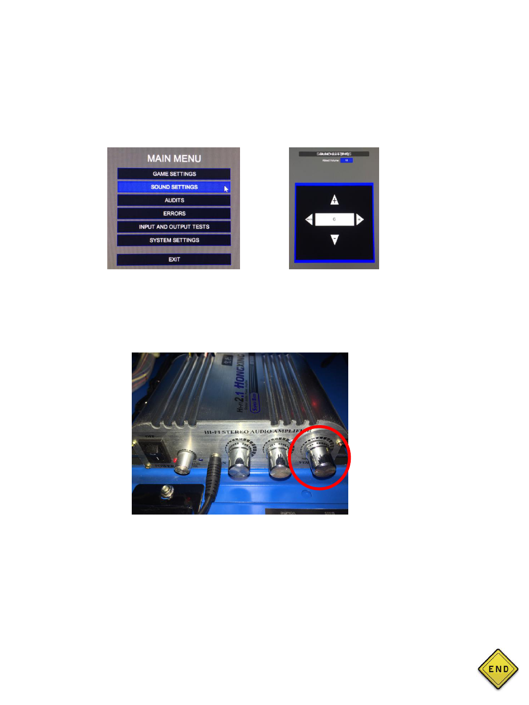
HOW TO ADJUST MASTER/ATTRACT VOLUME
STEP 1: Adjusting the attract volume
• Put the keyboard dongle into PC1 and press the letter “O” on the keyboard to enter the
operator menu.
• Select “Sound Settings.”
• Adjust the attract volume using the up/down arrow keys on the keyboard.
STEP 2: Adjusting the Master Volume on the amplifier
• Locate the amplifier in the rear of the tower. It is located just right of the FB216 I/O board
• Adjust the far right knob to desired volume.
This is the end of this section. Click the button on the right to return to the main menu.
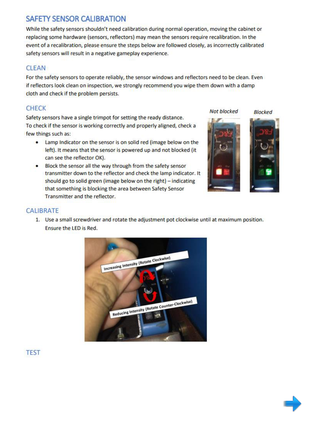
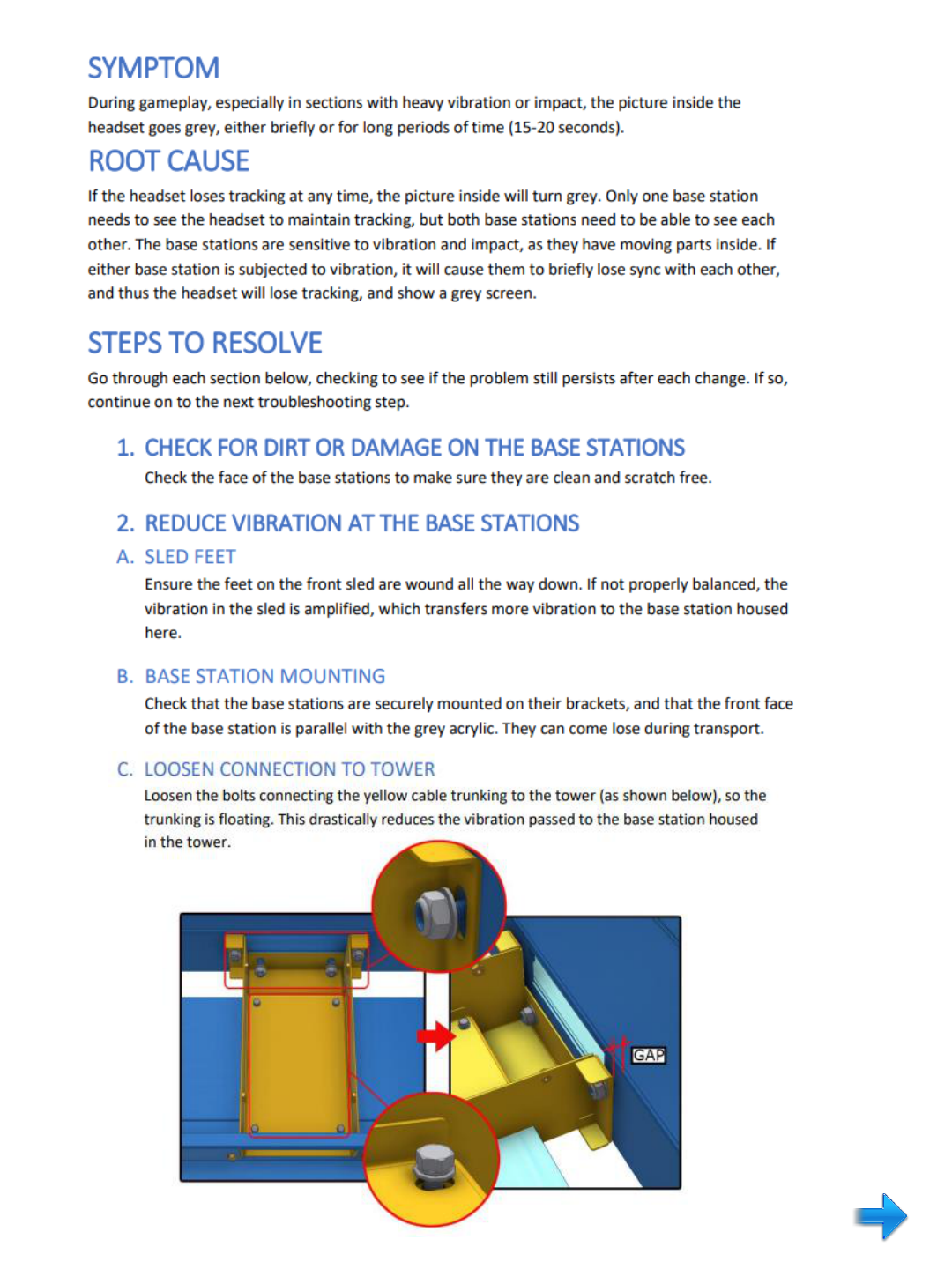
FURTHER TROUBLESHOOTING
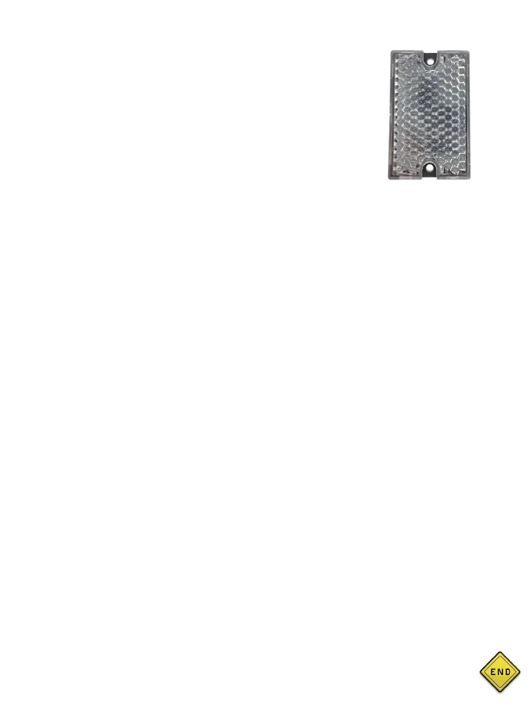
• Remove one of the reflectors from the ride and bring it close to the
sensor. If the sensor does not turn red, adjust the trimpot clockwise and
counterclockwise slowly.
• If the sensor turns red, it is most likely just out of alignment. Loosen the
mounting bolts to realign. Adjust the trimpot once again to find the
correct range.
• If the sensor stays green, you have a failed sensor and will need to
contact your distributor.
This is the end of this section. Click the button on the right to return to the main menu.
SYMPTOM: PC DOES NOT FULLY BOOT UP OR HAS INTERMITTENT FAILURES
STEP 1: Remove all cabling attached to the back of the PC, and remove the PC from the
cabinet.
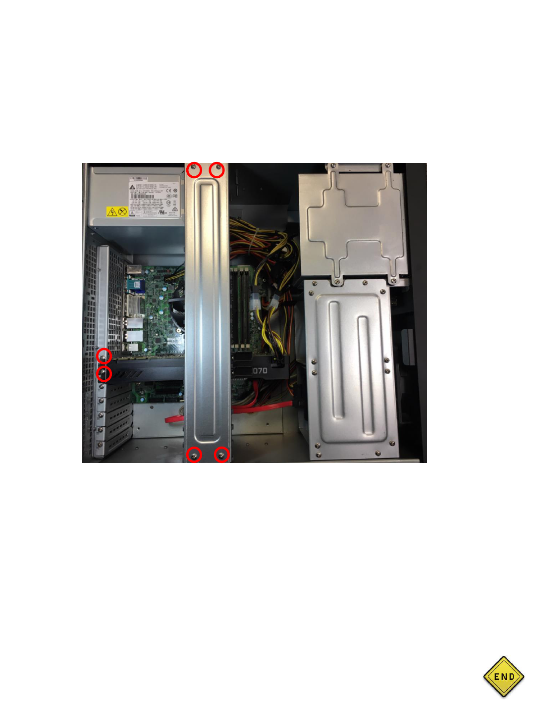
STEP 2: Remove the access cover and check for any loose connections inside.
• Remove the six screws in the image below which will give you access to the video card.
• Reseat the video card and reinstall screws.
• Make sure all connections are secure.
Video Card
STEP 3: Replace cover and reinstall the PC in the cabinet.
• Be sure to reconnect all cabling back into the rear of the PC exactly how it was before
removal.
TEST
• Power on the unit to see if the problem is resolved. If the power issue continues.
Contact your distributor.
This is the end of this section. Click the button on the right to return to the main menu.

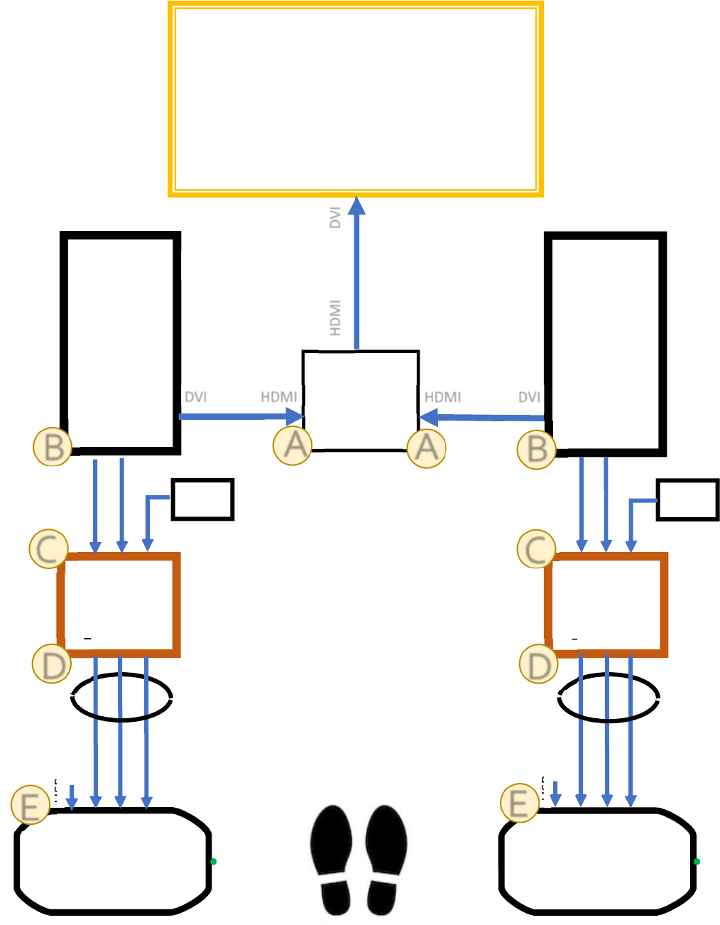
Virtual Rabbids
Video Flow Chart & Troubleshooting
PC2
PC1
Big Screen
HDMI
Video
Switch
DVI
HDMI
HDMI DVI
HDMI DVI
Link
B
ox
2
Link
B
ox
1
AC
Adapter
AC
Adapter
USB
USB
HDMI
HDMI
Headset 2
Headset 1
HDMI
HDMI
USB
USB
12vDC
12vDC
12vDC
12vDC
3-in-1
Cable #2
3-in-1
Cable #1
USB
NOT USED
USB
NOT USED
B
B
C
C
D
D
E
E
A
A
