
User’s Guide
5
SPL 1021 - SMART ideas - User Gu1 1 10/3/2007 3:39:06 PM
Trademark Notice
SMART Ideas, SMART Board, smarttech, the Smart logo and the
SMART Ideas logo are trademarks or registered trademarks of
SMART Technologies ULC in the U.S. and/or other countries. All
other third-party product and company names may be trademarks
of their respective owners.
Copyright Notice
© 1995-2007 SMART Technologies ULC. All rights reserved.
No part of this publication may be reproduced, transmitted,
transcribed, stored in a retrieval system or translated into any
language in any form by any means without the prior written
consent of SMART. Information in this manual is subject to change
without notice and does not represent a commitment on the part
of SMART.
U.S., Canadian and foreign patents pending.
If you have any questions about what constitutes legal use of this
product, please consult the license agreement that came with your
original software, or contact SMART Technologies ULC.
Printed in Canada 10/2007
SPL 1021 - SMART ideas - User Gu2 2 10/3/2007 3:39:57 PM

Table of Contents i
Table of Contents
Welcome to SMART Ideas® Software 1
About Concept Maps....................................................................................................................... 1
About This Guide ............................................................................................................................ 1
Creating a Diagram 3
Symbols .......................................................................................................................................... 3
Creating Symbols............................................................................................................................ 4
Rapidly Creating a Connected Diagram.......................................................................................... 4
Linking Symbols with Connectors ................................................................................................... 7
Labeling Connectors ....................................................................................................................... 9
Editing a Diagram 11
Selecting Symbols and Connectors ...............................................................................................11
Moving Symbols............................................................................................................................ 12
Changing Diagram Layout ............................................................................................................ 14
Aligning Symbols........................................................................................................................... 15
Distributing Symbols ..................................................................................................................... 16
Resizing Symbols.......................................................................................................................... 17
Resizing Symbols to Show All Text...............................................................................................18
Deleting Symbols and Connectors................................................................................................ 18
Cutting, Copying and Pasting Objects .......................................................................................... 19
Protecting Objects from Editing..................................................................................................... 19
Undoing Changes ......................................................................................................................... 20
Using Styles and Style Collections 21
Styles Overview ............................................................................................................................ 21
Formatting Symbols with Styles.................................................................................................... 21
Formatting Connectors with Styles................................................................................................ 24
About Style Collections ................................................................................................................. 26
Creating Style Collections ............................................................................................................. 26
Adding Styles to Style Collections................................................................................................. 27
Importing Style Collections............................................................................................................ 29
Converting Style Collections ......................................................................................................... 29
Saving Style Collections as .ips Files............................................................................................ 30
Showing and Editing Style Names ................................................................................................ 30
Customizing Your Diagram 33
Changing the Appearance of Symbols.......................................................................................... 33
Changing the Appearance of Connectors..................................................................................... 34
Adding Two-Color Patterns and Gradients to Symbol Fills ........................................................... 35
Using StylePaint to Copy an Object’s Formatting ......................................................................... 36
Adding a Video File to a Symbol................................................................................................... 37
Adding a Sound File to a Symbol.................................................................................................. 39
Adding a Note to a Symbol ........................................................................................................... 41
Making a Symbol Transparent ...................................................................................................... 42
Adding a Shadow to a Symbol...................................................................................................... 43
Using an Imported Image as a Symbol......................................................................................... 44
Using Clip Art as a Symbol ........................................................................................................... 45

ii Table of Contents
Importing Images into the Clip Art Gallery .................................................................................... 46
Searching for Clip Art and Cliplets ................................................................................................ 47
Using Interactive Cliplets............................................................................................................... 48
Inserting Cliplets............................................................................................................................ 49
Grouping Symbols with Sticky Symbols........................................................................................ 50
Adding a Legend to Your Diagram................................................................................................ 52
Inserting a Blank Legend .............................................................................................................. 53
Creating a Legend from a Style Collection.................................................................................... 53
Converting a Legend to a Custom Style Collection....................................................................... 54
Getting to Know the Workspace 55
Sub-Level Workspaces ................................................................................................................. 55
Tools for Navigating in Your Sub-Level Workspaces..................................................................... 56
Using the Navigator in the Gallery Toolbar.................................................................................... 56
Viewing Sub-Levels....................................................................................................................... 57
Workspace Views.......................................................................................................................... 57
Maximizing the Workspace ........................................................................................................... 59
Using the Workspace Grid ............................................................................................................ 60
Changing the Background Color...................................................................................................60
Applying a Color Scheme to Your Diagram................................................................................... 61
Changing Skins............................................................................................................................. 63
Using the Zoom Feature ............................................................................................................... 64
Moving Around the Workspace.....................................................................................................64
Shrinking and Expanding Diagram Trees...................................................................................... 65
Working with Text 67
Editing Text.................................................................................................................................... 67
Formatting Text ............................................................................................................................. 68
Checking Your Spelling ................................................................................................................. 68
Finding and Replacing Text........................................................................................................... 69
Changing Text Placement ............................................................................................................. 70
Adding Layers and Links to Diagrams 71
Creating Layered Diagrams .......................................................................................................... 71
Showing Sub-Levels ..................................................................................................................... 73
Navigating through Symbol Layers ............................................................................................... 74
Creating Links to Websites, Files or Other Diagram Levels.......................................................... 74
Removing and Replacing Links..................................................................................................... 77
Working in Outline View 79
Understanding Outline View.......................................................................................................... 79
Creating Topics ............................................................................................................................. 80
Creating Notes, Links and Sub-levels........................................................................................... 81
Editing Text in Outline View........................................................................................................... 82
Reorganizing Your Outline ............................................................................................................ 83
Hiding and Revealing Topics in Outline View................................................................................ 83
File Management 85
Creating a New SMART Ideas File ............................................................................................... 85
Opening a SMART Ideas File ....................................................................................................... 86
Saving a SMART Ideas File.......................................................................................................... 86

Table of Contents iii
Exporting a SMART Ideas File to Word, WordPerfect, AppleWorks or a Plain Text File .............. 86
Exporting Workspace Views to the Web ....................................................................................... 88
Printing a Diagram ........................................................................................................................ 88
Using Print Preview....................................................................................................................... 89
Using Templates in SMART Ideas Software ................................................................................. 90
Using SMART Ideas Software on a SMART Board Interactive Whiteboard 93
Creating Symbols with a Pen Tray Pen ........................................................................................ 93
Connecting Symbols with a Pen Tray Pen.................................................................................... 94
Editing with a Pen Tray Pen.......................................................................................................... 96
Appendix B: Using SMART Ideas Software on a Tablet PC 97
Writing or Drawing using the Tablet Pen....................................................................................... 97
Create Circle and Square Symbols Using the Tablet Pen............................................................. 99
Selecting Objects Using the Tablet Pen...................................................................................... 100
Grouping and Ungrouping Ink.....................................................................................................101
Connecting Symbols with Your Tablet Pen ................................................................................. 102
Erasing Objects with Your Tablet Pen ......................................................................................... 103
Customer Support 105
Online Support............................................................................................................................ 105
Training ....................................................................................................................................... 105
Contacting SMART Technical Support........................................................................................ 105
General Inquiries......................................................................................................................... 105
Registration................................................................................................................................. 105
Index 107

iv Table of Contents
Welcome to SMART Ideas Software 1
Welcome to SMART Ideas® Software
About Concept Maps
A concept map lets you capture and display ideas and their relationships in a clear, graphical way,
with an immediacy that’s not possible with formal, linear text.
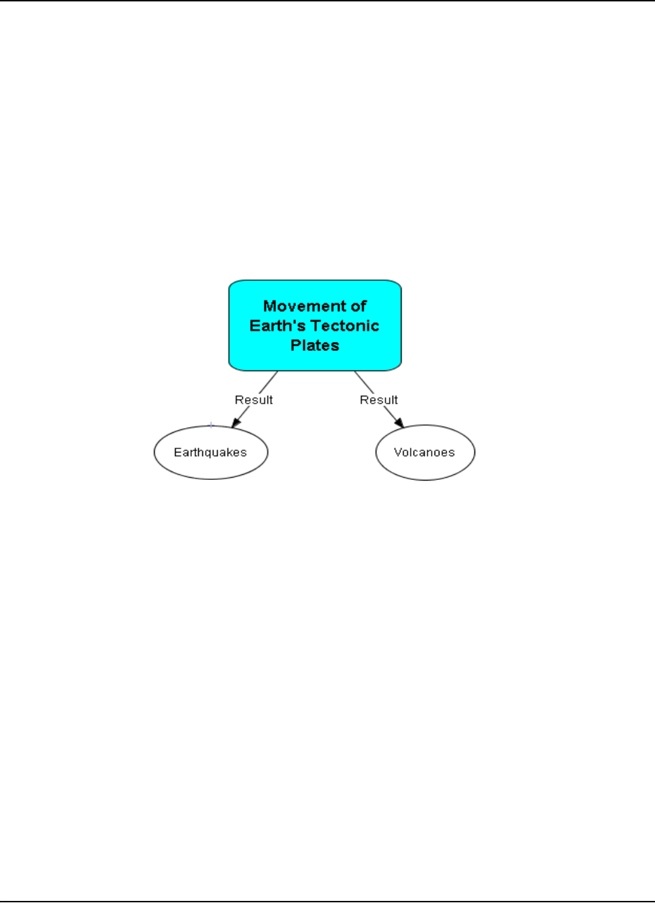
For example, a geology teacher in front of a class might say: “The movement of the earth’s
tectonic plates results in earthquakes and volcanic activity.” To help get her point across, she could
write this sentence on a whiteboard. However, the sentence might have little impact on a group of
restless students.
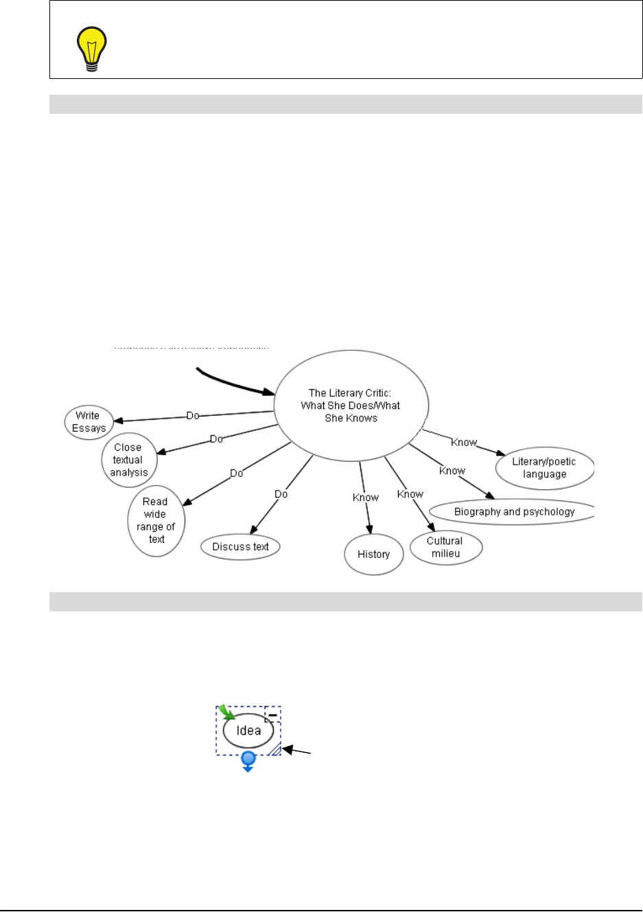
Instead, she could use SMART Ideas® software to create this simple cause-and-effect concept
map:
The effectiveness of this concept map visually reinforces her spoken words, but its effectiveness
goes well beyond that of a simple visual aid. By liberating ideas from the limitations of syntax,
concept maps can deepen students’ understanding and provoke genuine interest. With SMART
Ideas software, you can make your concept maps simple and austere to show the basic
connections between ideas or you can make them as elaborate and eye-catching as you like.
About This Guide
In SMART Ideas software, and throughout this guide, we refer to the concept maps you create with
SMART Ideas software as diagrams.
First, you’ll learn how to create and edit simple diagrams with SMART Ideas software. Then you’ll
go beyond the basics to learn about the this program’s many advanced features, like importing clip
art and other graphics, using the Outline view, adding hyperlinks, and creating diagrams with
multiple levels.

2 Welcome to SMART Ideas Software

Creating a Diagram 3
Creating a Diagram
The SMART Ideas workspace is designed for quick, easy and flexible diagram creation. A diagram
is made up of two components: symbols and connectors.
Symbols
In SMART Ideas software, a symbol is a graphical object, such as a circle, a square or a picture,
that encloses a text message. This message can be a few words or a phrase. However, the more
concise the message, the better.
You can make your symbols more distinctive and meaningful by using different colors and shapes.
For example, if you create a diagram showing the titles of Shakespeare’s major plays categorized
by genre, you could represent comedies as transparent circles, tragedies as dark squares and
history plays as shaded triangles. This would allow your students to easily identify the genre of
each play at a glance.
To enhance a symbol even further, try integrating it with an image. While SMART Ideas software
comes with a clip art collection, you can use any collection of graphics or clip art as your image
source.
For example, the image of Shakespeare in the previous diagram adds historical context. You could
inform the class that this image is based on a portrait that appears on the cover of the first-folio
edition of Shakespeare’s collected plays, printed in 1623. You could then talk about the
significance of this publication, and even add an Internet link to an electronic version of the first
folio edition. By adding one image, you’ve transformed your diagram into an effective learning
resource.
4 Creating a Diagram
You can make a symbol as simple or as elaborate as you like. In this section, we’ll focus on how to
create diagrams using simple symbols. In a later section, you’ll learn how to create diagrams using
much more elaborate symbols.
Creating Symbols
After you start SMART Ideas software, the New SMART Ideas diagram dialog box appears. Click
the Open button and a new, untitled workspace appears, ready for your input.
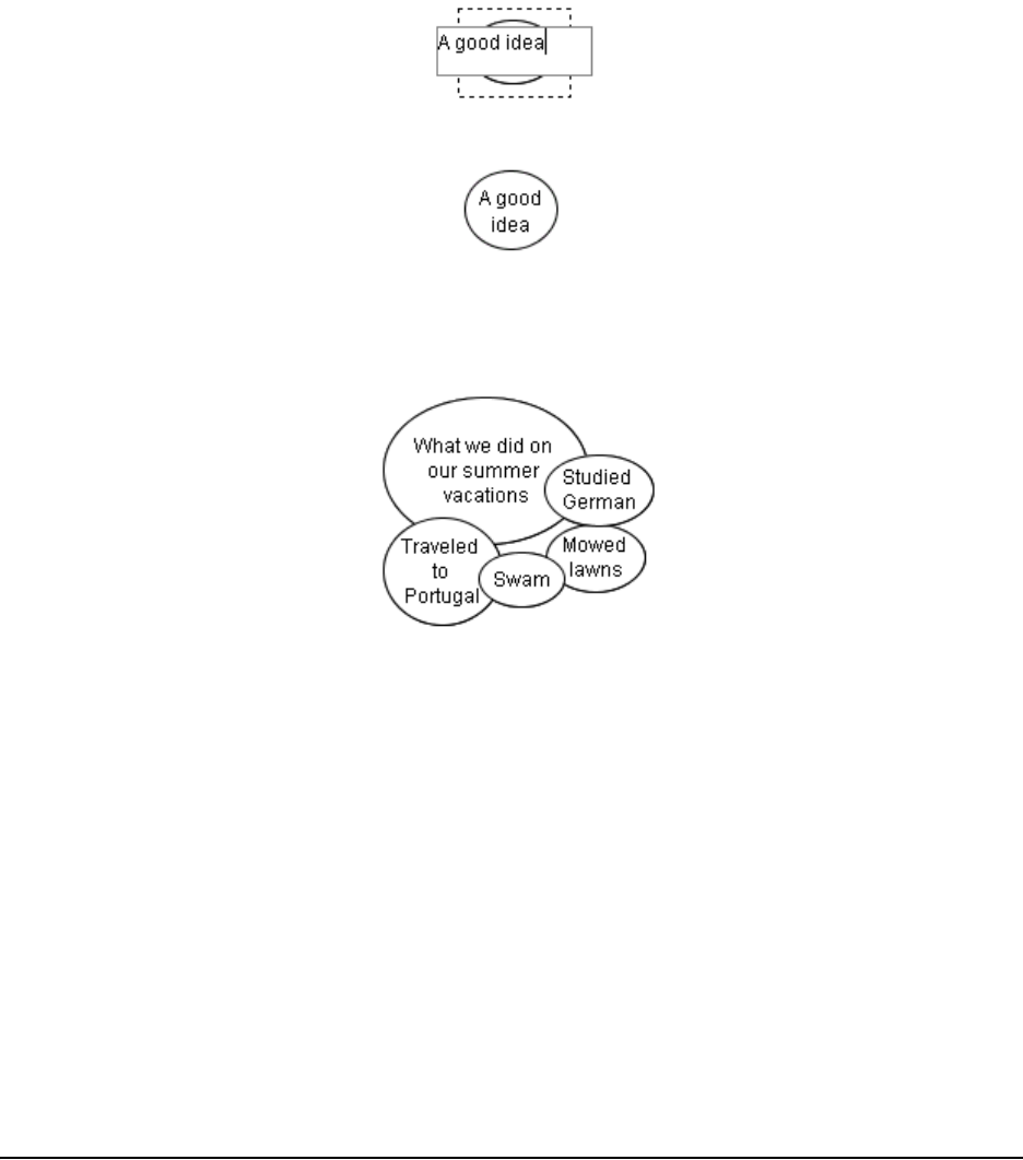
Type some short words. Your text appears inside a text box.
Press the ENTER key on your keyboard. The text appears inside a circle.
Type another text message. Press the ENTER key again and your second message appears
inside another circle. If you continue to type and press the ENTER key, you’ll find you’ve created a
diagram of overlapping, disconnected symbols that you can arrange and connect later.
Rapidly Creating a Connected Diagram
If you prefer, you can rapidly create a diagram of arranged and connected symbols using the
QuickCreate menu option. This method is ideal for brainstorming sessions. Click the QuickCreate
button, ask your students for their ideas on a topic, and use your keyboard to immediately capture
those ideas in a fully connected, well-organized diagram. Each time you press ENTER another
connected symbol appears enclosing your text. With QuickCreate, the selected symbol becomes
the primary symbol. When you press ENTER to create another symbol, it automatically connects
to the primary symbol.
You can also choose the layout of your diagram—before you begin. Click the Layout drop-down
arrow and select from one of ten available patterns before you start creating the diagram.

Creating a Diagram 5
As you construct your diagram at your keyboard, it develops on the screen in the selected layout.
If you’re not satisfied with the pattern after the diagram has been created, you can easily change
the pattern with a click of the Layout button.
NOTE: With QuickCreate, your symbols must contain text. Blank symbols can’t be part of a
diagram created with this feature. Also, the shape and color of the symbols you create is
determined by the currently selected symbol style.
1. Click the QuickCreate button on the Standard toolbar.
2. Click the Layout arrow on the Standard toolbar, and then select a layout pattern.
3. Type a text message, and then press the ENTER key on your keyboard.
The message appears as a selected symbol with an adjacent text box.
4. Type another message, and then press the ENTER key.
This message appears as a symbol connected to the first symbol.
5. Type another message, and then press ENTER.
This message appears as a symbol connected to the first symbol.
Two Possible Layouts for Your Diagram
To rapidly create a diagram of connected symbols
6 Creating a Diagram
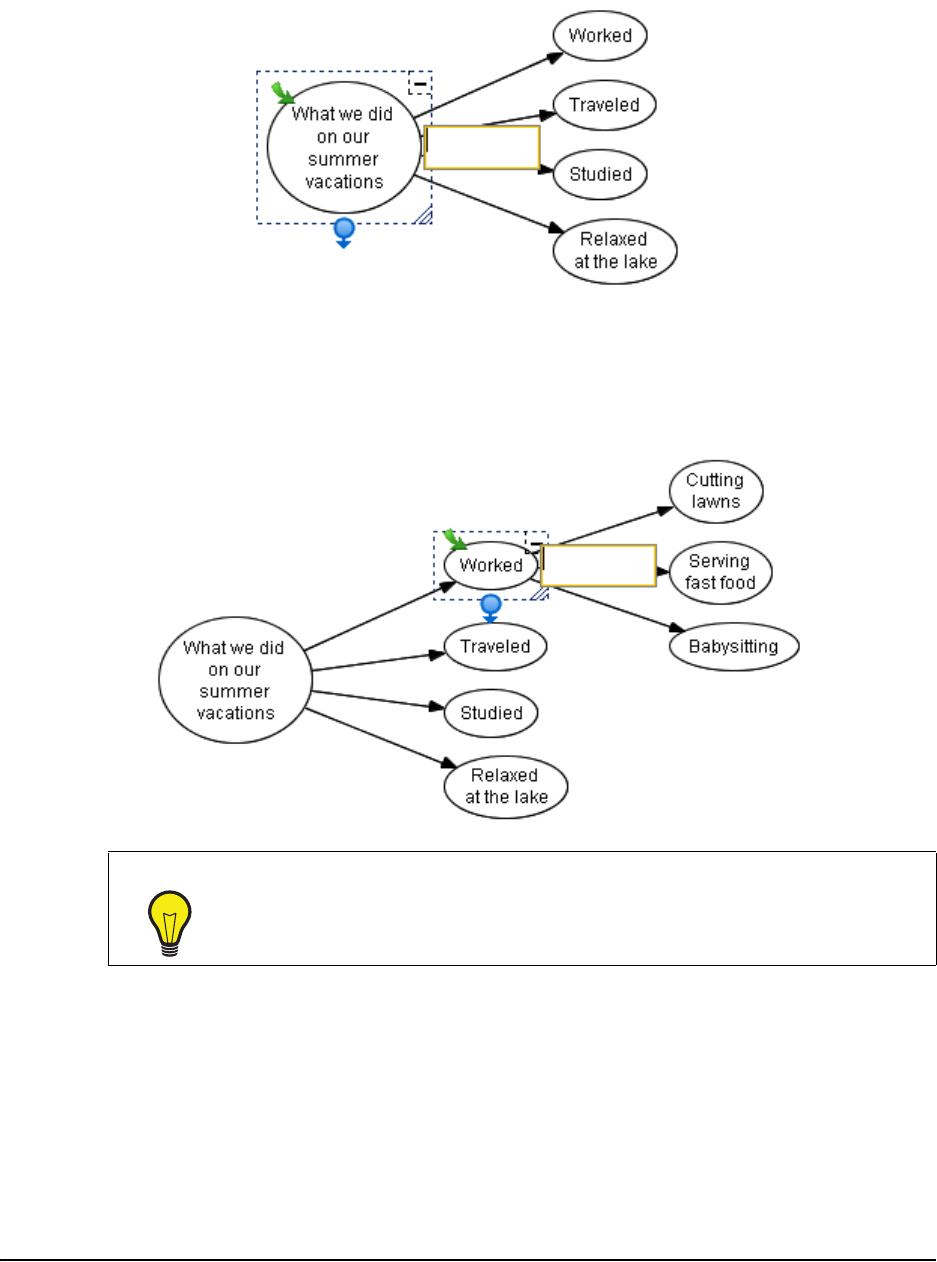
6. Continue to enter text (pressing ENTER to create each symbol) to create a diagram that
develops in your selected layout pattern.
OR
Select any symbol in the diagram to make new symbols branch from it. For example, select
the symbol labeled Worked to make it a root symbol for a subsequent tree of symbols (see the
following figure).
7. Click the QuickCreate button again when you finish the brainstorming session to deactivate
this feature.
8. To rearrange the diagram in a different pattern, select the primary symbol, click the Layout
arrow, and then select another pattern.
TIPS
• Use the UP, DOWN, LEFT and RIGHT ARROW keys to navigate through
the symbols in the current tree.
• Use the TAB key to jump to the root of the next tree.
Creating a Diagram 7
Linking Symbols with Connectors
To show a relationship between symbols, use a connector. A connector is a line that links two
symbols. A connector can be labeled or unlabeled; thin or thick; solid or dashed; straight, angled
or curved.
Connectors are also dynamic components of your SMART Ideas diagram: When you move a
symbol that’s connected to another symbol, the connector moves with it. However, if the
relationships between symbols change, you can move the connectors independently of their
associated symbols.
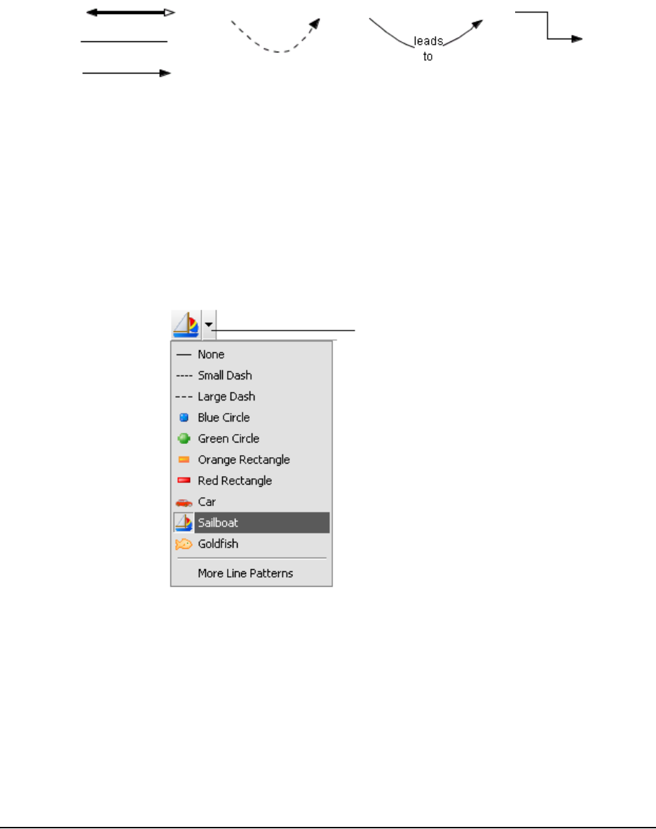
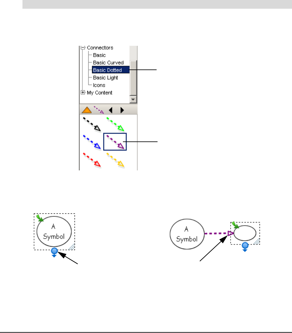
Along with a full range of standard line-based connectors, SMART Ideas software comes with a
more whimsical set of connector called Deluxe Connectors that’s designed to stimulate the interest
of your students. You’ll find all the available connector styles in the Connectors category under
Style Collections in the Gallery toolbar.
The connector type that you select remains in effect until you select another style. For example, if
you select the Sailboat connector style, all new connectors are lines of sailboats until you change
the style again. For more information on changing connector appearance, turn to page 34.
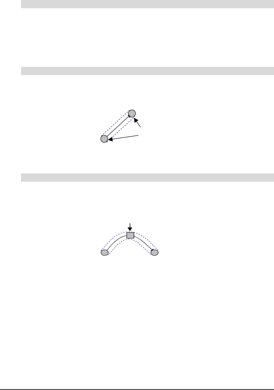
Connector Arrow
8 Creating a Diagram
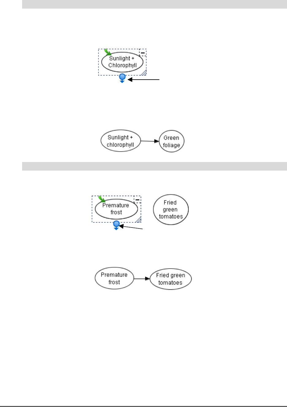
1. Select a symbol.
2. Click the Connector button at the bottom of the selection rectangle, and then drag to the spot
where you want the new, connected symbol to appear.
An empty text box appears, connected to the original symbol by a selected connector.
3. Enter text, and then press the ENTER key on your keyboard.
A new symbol appears. This symbol is connected to the original symbol with a connector.
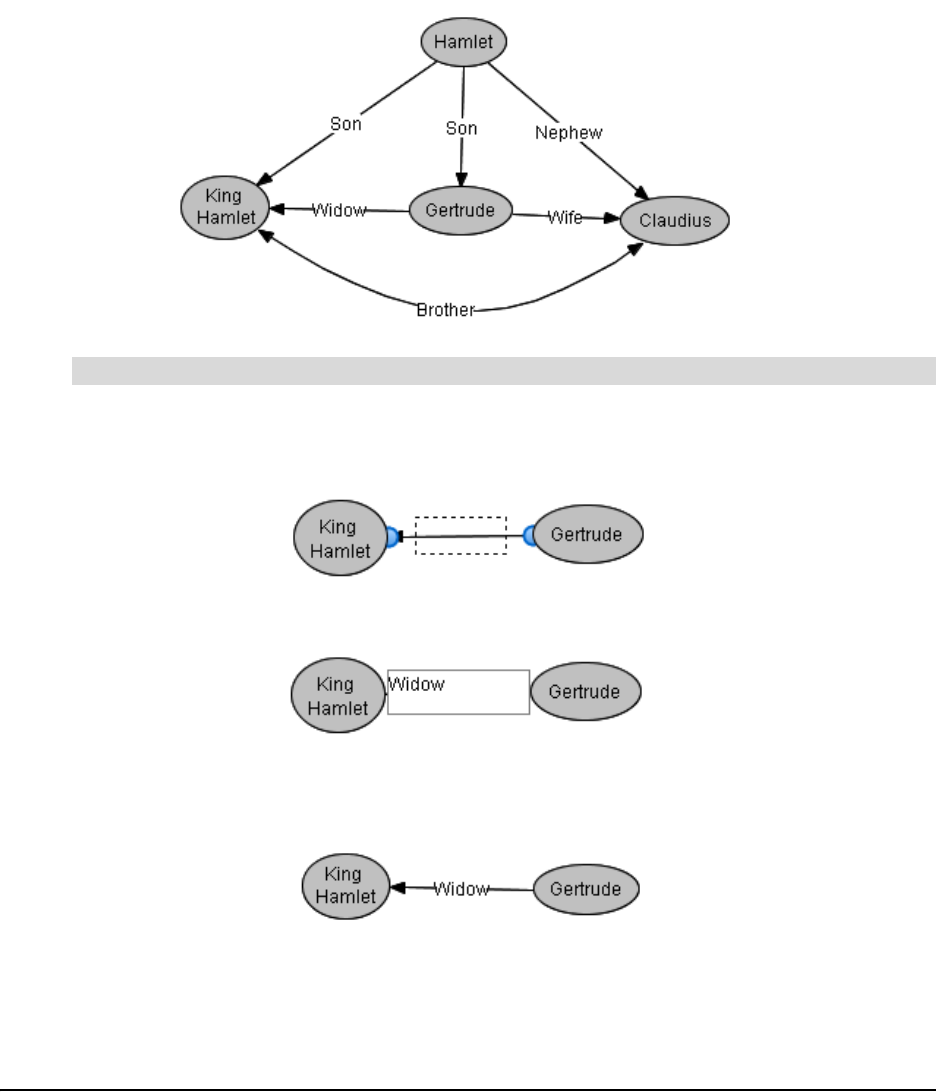
1. Select either symbol.
2. Click the Connector button, and then drag the connector to the second symbol.
A connector now links both symbols.
To create a new, connected symbol
To connect two symbols
Click here
Click here and drag
Creating a Diagram 9
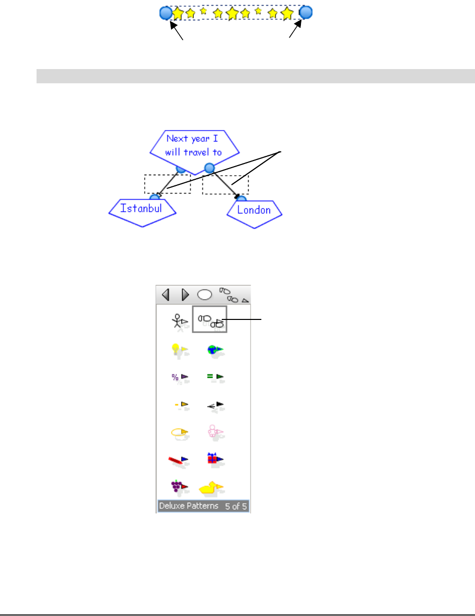
Labeling Connectors
The primary function of a connector is to show how two symbols are linked. However, you may
also want to label a connector with text to more explicitly describe the relationship between those
two symbols.
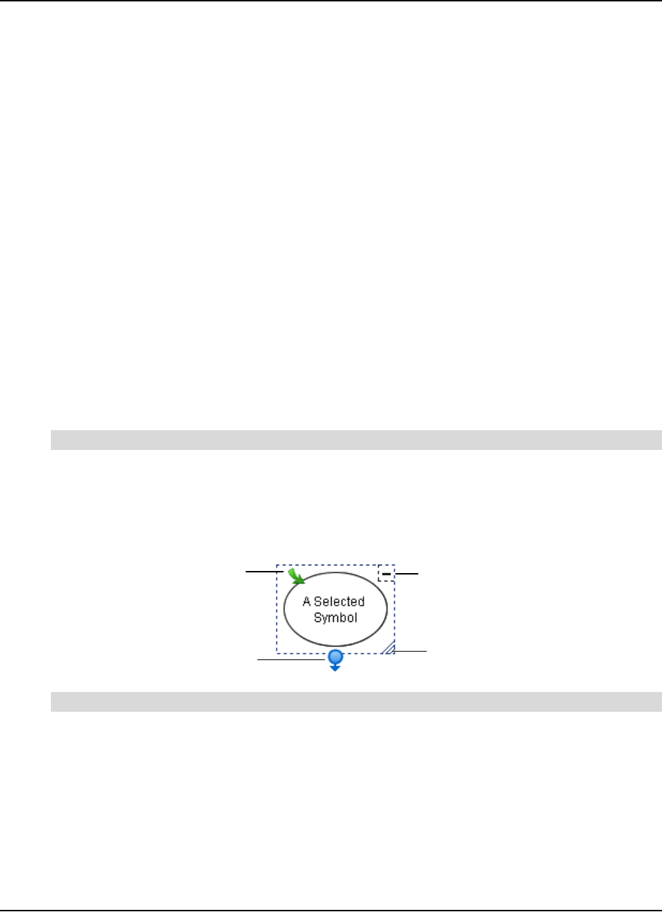
For example, students often have difficulty understanding the complex interrelationships among
the characters in Hamlet. Creating a diagram with labeled connectors, such as the one that
follows, would help a class grasp these sometimes confusing relationships.
1. Select the connector.
A text box appears in the middle of the connector.
2. Type the label in the text box.
3. Press the ENTER key on your keyboard.
The label appears in the center of the connector.
To label a connector

10 Creating a Diagram
Editing a Diagram 11
Editing a Diagram
This section focuses on how to:
• select symbols and connectors (see below)
• move symbols (page 12)
• rearrange diagrams (page 14)
• align symbols (page 15)
• distribute symbols (page 16)
• resize symbols (page 17)
• delete symbols and connectors (page 18)
• cut, copy and paste symbols (page 19)
• protect objects from symbols (page 19)
• undo changes (page 20)
Selecting Symbols and Connectors
To work with a symbol or connector, you must first select it. If you like, you can change several
symbols or connectors simultaneously by selecting them at the same time or select all objects in
the current workspace.
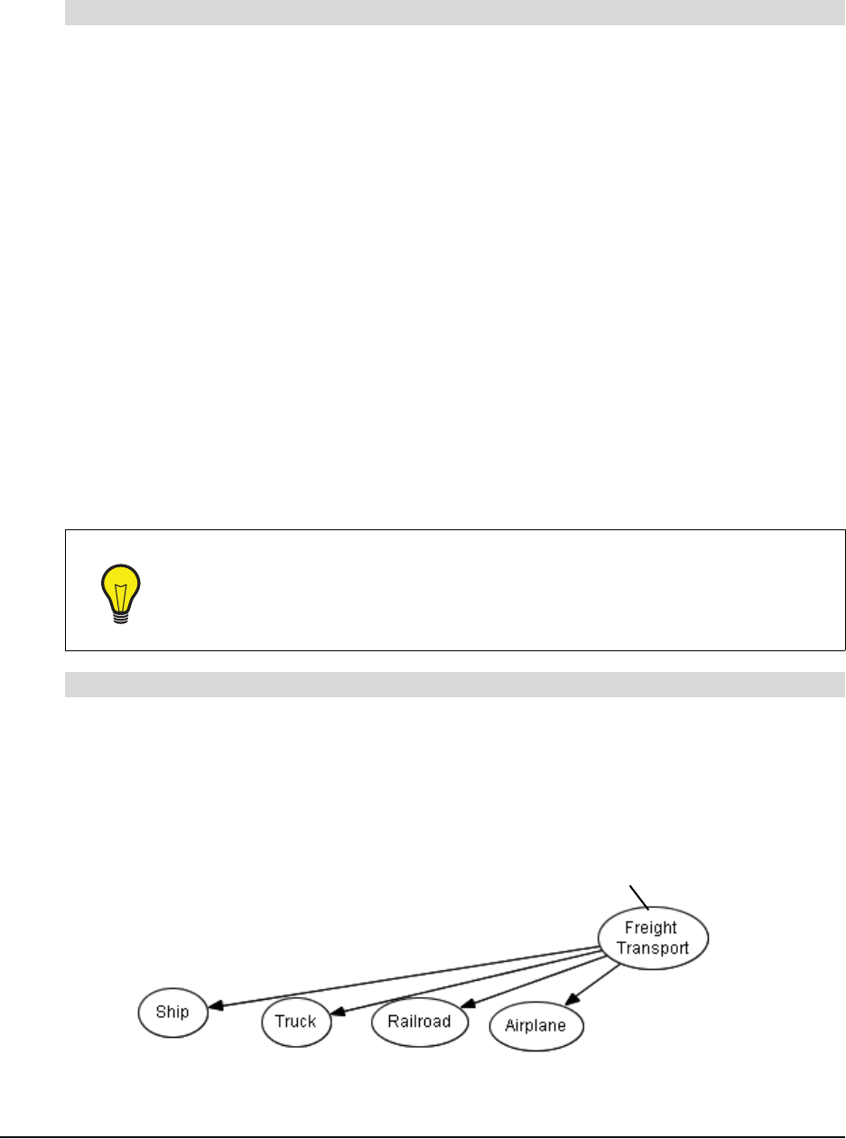
1. Move the cursor over the object you want to select and click once.
If the object is a symbol, a selection rectangle with four icons encloses it. You can click these
icons to perform a variety of operations, including resizing the symbol, creating connectors
and opening sub-levels.
Press and hold the mouse button. Drag the pointer to draw a rectangle around the objects that you
want to select.
OR
Use the CTRL or SHIFT key to make multiple selections, as follows:
a. Click the first object to select it.
A selection rectangle encloses the object.
To select a symbol or connector
To select multiple symbols and/or connectors
Open Sub-level
Collapse
Diagram
Resize
Create a Connector
12 Editing a Diagram
b. Hold down the CTRL key or the SHIFT key, and then click any other objects you want to
select.
Select Edit > Select All.
OR
Press CTRL+A.
Selection rectangles enclose all objects on the page.
Moving Symbols
It’s easy to rearrange your diagram to suit a developing train of thought.
When you select a symbol, only that symbol moves; any connected symbols remain in place, and
any associated connector automatically lengthen, contract or rotate as required. You can also
move a connector separately from the symbol it’s connected to.
To move an entire diagram of symbols and connectors, first select all the objects, and then press
and hold the mouse button and drag.
If your diagram contains curved connectors, not only can you move them—you can reshape them
to accommodate altered symbol configurations.
1. Click on the symbol.
2. Keep the mouse button depressed, drag the symbol elsewhere, and then release.
NOTE: If the symbol is linked to other symbols by connectors, they rotate and change length
(as required by the move) while the associated symbols remain fixed in place.
To select all objects
TIP
You may want to stack symbols by moving them on top of one another. If you do
this, first clear the selection of View > Sub-levels. If you try to stack symbols while
the Sub-levels menu option is selected, the symbols drop into sub-levels rather
than being stacked on top of one another in the current level. See page 57 for more
information on using the Sub-levels menu option.
To move a symbol
Moving Symbol
Fixed Symbols
Connectors stretch to accommodate
moving symbol
Editing a Diagram 13
1. Drag the pointer while holding the mouse button down to draw a rectangle around the symbols
you want to select.
NOTE: When you do this, the connectors are automatically selected.
2. Click any of the selected symbols.
3. Hold down the mouse button, and then drag the objects to their new position.
1. Select the connector.
A blue outline with blue spheres at both ends encloses the connector.
2. Click, hold, and then drag either sphere to another symbol.
3. Release the mouse button.
1. Select the curved connector.
2. Click, hold, and then drag the blue square to change the angle of the connector curve.
3. Release the mouse button when the curve is the desired shape.
To move multiple symbols and connectors (diagram move)
To connect to another symbol
To reshape a curved connector
Click, hold
and drag
Click, hold and drag
14 Editing a Diagram
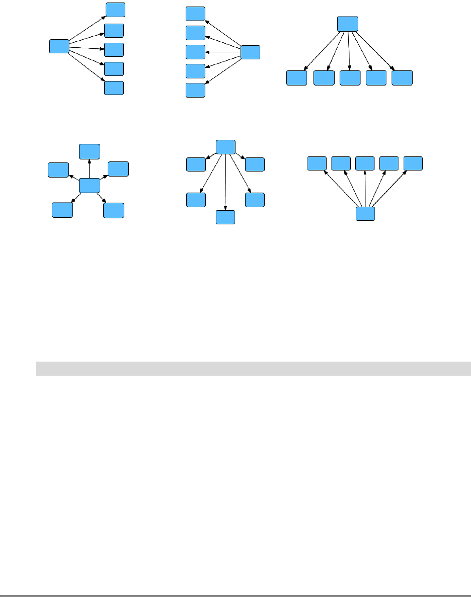
Changing Diagram Layout
The Layout feature of SMART Ideas software allows you to instantly arrange individual diagrams
(or all the diagrams on the page) in ten possible layout patterns. Six of the available patterns are
shown below.
When paired with the QuickCreate feature (page 4), the Layout feature lets you specify the
arrangement of a diagram before you create it. However, you can also use it to change the layout
of a diagram (or a full page of diagrams) after you’ve created it.
You can also use the Layout feature to change the connector shapes from straight to right-angled.
NOTE: If you apply a layout to an entire page, all your diagrams are centered on the page.
1. Select one or more diagrams.
2. Click the Layout arrow on the Standard toolbar.
3. Click one of the ten layout buttons to select a layout.
SMART Ideas software modifies the layout of all selected diagrams.
To change the layout of an existing diagram(s)
Right Tree Left Tree Bottom Tree
Top Tree
Radial
Ring
Editing a Diagram 15
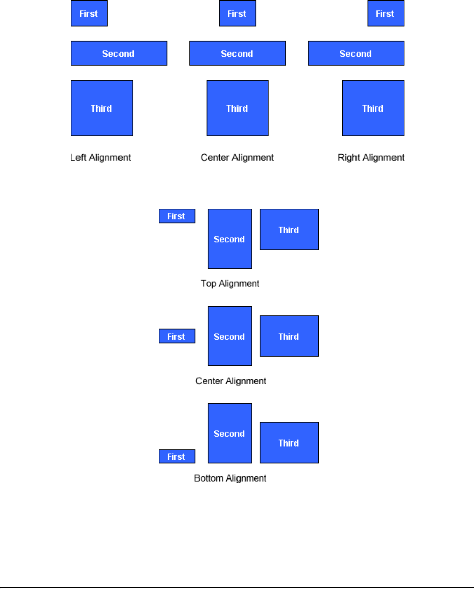
Aligning Symbols
You can use the Align Symbols menu option to horizontally or vertically align any number of
selected objects.
You can horizontally align objects along the left, the vertical-center or the right.
You can vertically align objects along the top, the horizontal-center or the bottom.
16 Editing a Diagram
1. Select the symbols you want to align.
2. Click the Align button on the Standard toolbar.
OR
Select Symbol > Align.
3. Select the alignment option you'd like.
OR
Select Automatic to align the symbols based on their current arrangement: If the selected
objects are mainly vertical, they align vertically; if they are mainly horizontal, they align
horizontally.
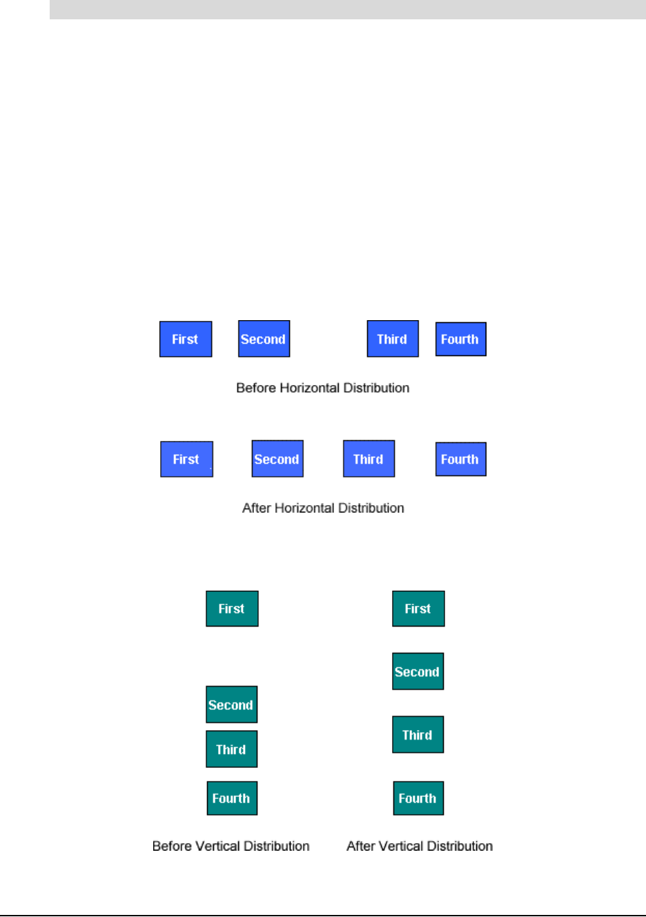
Distributing Symbols
You can use the Distribute Symbols menu option to evenly distribute symbols horizontally.
You can also use the Distribute Symbols menu option to evenly distribute symbols vertically.
To align symbols
Editing a Diagram 17
1. Select the objects you want to distribute.
2. Select Symbol > Distribute Symbols > Vertically.
OR
Select Symbol > Distribute Symbols > Horizontally.
Resizing Symbols
In addition to creating symbols of different colors and shapes, you also create symbols of different
sizes to graphically demonstrate idea hierarchy. For example, you can tell at a glance that a
symbol represents the central idea if it is larger than the other symbols in the diagram.
1. Select one or more symbols.
2. Click, hold, and then drag the Resize icon (in the lower-right corner of the selected symbol) to
enlarge or contract the symbol.
NOTE: To resize multiple, selected symbols at the same time, drag the Resize icon of any
single symbol in the group.
3. Release the mouse button.
TIP
To arrange objects neatly on your diagram, use the Distribute Symbols menu
option in conjunction with the Align Symbols menu option.
To distribute objects evenly
To resize a symbol
Larger symbol indicates its
relative importance
Click, hold and drag
18 Editing a Diagram
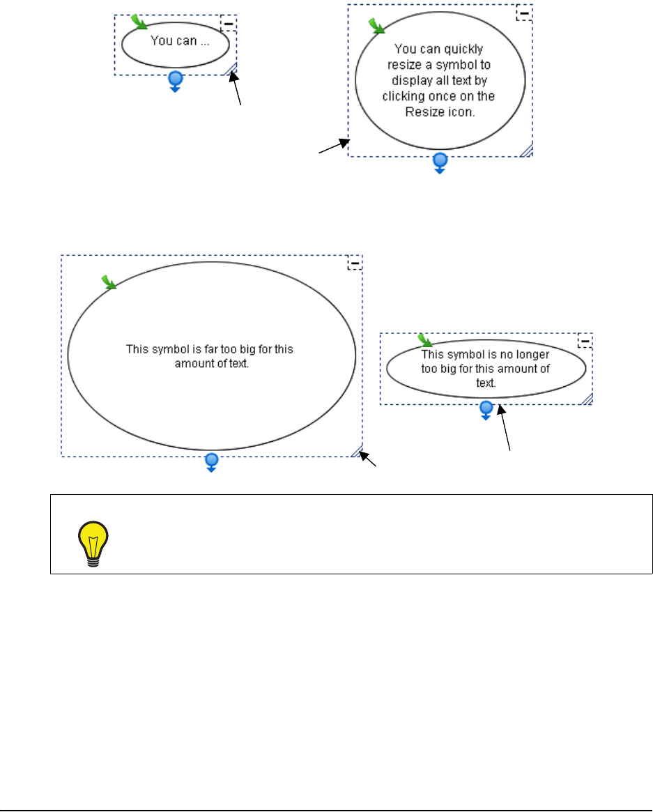
Resizing Symbols to Show All Text
You can type a lot of text into a symbol. However, when the symbol is small and can’t
accommodate all the text you’ve entered, ellipsis points (…) indicate the text that isn’t shown. To
enlarge the symbol so all text is displayed, click the Resize icon in the lower-right corner of the
selected symbol.
If a symbol is much larger than the text requires, click the Resize icon to shrink the symbol to
neatly fit around the text.
Deleting Symbols and Connectors
Deleting an object may have an impact beyond the simple disappearance of the object.
• If a symbol has one or more sub-levels, those sub-levels (and all the objects on them) are also
deleted.
• If a symbol has a hyperlink associated with it—for example, if it links to a file or website—that
link is lost when you delete the symbol.
Deleting a connector, however, affects only that connector. The symbols on either side remain
intact.
TIP
For lengthier text entries, attach a note to the symbol instead. When you move your
mouse pointer over the Note icon, the note appears in an editable text box. For
more information, see page 81.
Click here…
…for this result
Click here…
…
for this result

Editing a Diagram 19
1. Select one or more objects.
2. Click the Delete button on the Standard toolbar.
The selected object(s) disappears.
Cutting, Copying and Pasting Objects
You can use the Cut, Copy and Paste functions to duplicate or move any object in your current
workspace to another diagram, sub-level or application.
1. Select one or more objects.
2. Click the Cut or Copy button on the Standard toolbar.
OR
Select Edit > Cut or Edit > Copy.
NOTE: If you’re copying a symbol with an associated sub-level, you’ll be asked if you want to
copy the sub-level in addition to the symbol itself. Click the Yes button to copy the sub-level.
3. Click the Paste button on the Standard toolbar.
OR
Select Edit > Paste.
The object appears at the cursor insertion point.
Protecting Objects from Editing
You can protect an object or an entire group of objects from editing with the Make Background
menu option. This menu option moves selected objects into the virtual background, out of reach of
the selection tool.
1. Select the objects that you want to send to the background.
2. Select Tools > Make Background.
The object or objects that you selected are now part of the background (and are no longer
selectable).
1. Select Tools > Retrieve Background.
The object or objects that you selected are now part of the foreground and are selectable.
To delete an object
To cut/copy and paste an object
To protect an object from editing
To restore protected objects to the foreground

20 Editing a Diagram
Undoing Changes
If you make a mistake (or simply change your mind), you can reverse your previous actions. You
can also change your mind again and reinstate a revoked action.
Click the Undo button on the Standard toolbar.
OR
Select Edit > Undo.
Select Edit > Redo.
To undo the effect of the last action
To redo a revoked action

Using Styles and Style Collections 21
Using Styles and Style Collections
This section tells you about:
• styles (see below)
• formatting symbols with styles (page 21)
• formatting connectors with styles (page 24)
• style collections (page 26)
• creating style collections (page 26)
• adding styles to style collections (page 27)
• importing style collections (page 29)
• converting style collections (page 29)
• saving a style collection as an .IPS file (page 30)
• showing and editing style names (page 30)
Styles Overview
Suppose you’ve spent a few minutes changing the appearance of a symbol (or a connector) to
look exactly the way you want.
You’ve changed the fill color of the symbol, added a unique color outline, chosen a distinctive
shape, and made it 50% transparent. You may now want several other symbols to look exactly the
same.
You could select those symbols and format each one in the same way, but that takes time, and it
can be difficult to duplicate subtle shades of color with precision. Also, if you decide to change a
small aspect of one symbol, you must repeat the same formatting tasks for each of them. Instead,
you can save the original formatting in the form of a symbol style, and then apply the style to other
symbols you want to share the same appearance.
A style is a collection of characteristics that you can apply to any symbol in the workspace.
SMART Ideas comes with a wide array of styles but you can also create collections of your own
customized styles. The new styles you create are made available each time you start up SMART
Ideas software.
Formatting Symbols with Styles
Use the style palette in the Gallery toolbar (on the left side of the workspace) to choose the shape
and color of a symbol before you create it. After you select a style, every symbol that you create
thereafter has the characteristics of that style, until you select another style.
22 Using Styles and Style Collections
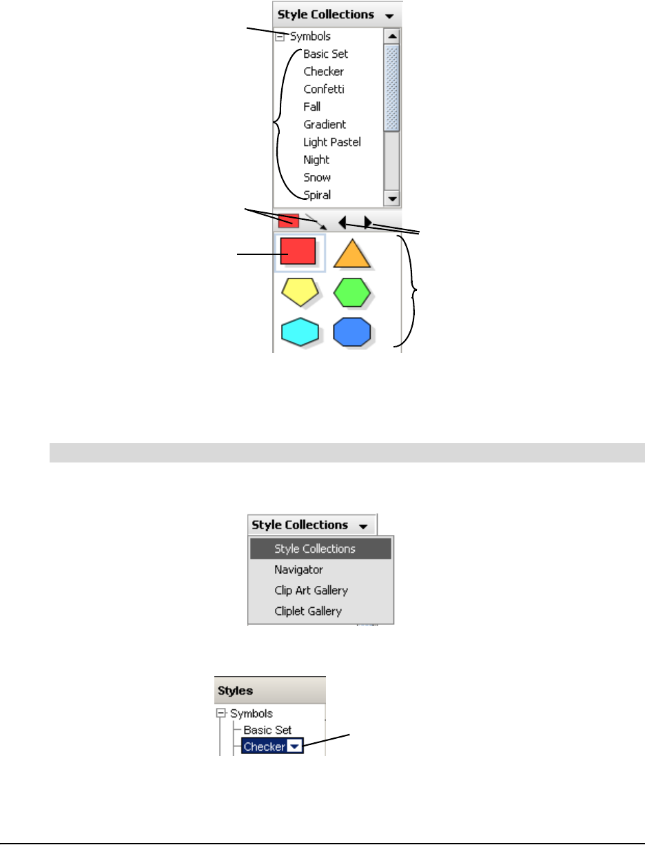
The currently selected symbol and connector style appear in preview form at the top of the style
palette as Preview buttons. When you’re exploring other style collections, you can return to the
style collection that contains the currently selected style by clicking on a Preview button.
The Back and Forward arrows at the top of the palette allow you to view all the styles in all style
collections, page by page. If a style collection contains only a few styles, clicking the Forward
button takes you to the first page of styles in the next style collection.
1. Click the drop-down arrow at the top of the Gallery toolbar, and then select Style Collections.
2. Expand the Symbols category, and then select a style collection.
To create a new symbol based on a style
Currently Selected Style
Preview Buttons
Back and Forward
Buttons
Currently Selected Category
Style Collection List
Style Palette
Selected Style
Collection
Using Styles and Style Collections 23
3. Select a style from the style palette.
4. Click in the workspace, type a message, and then press ENTER.
OR
If you prefer to create a symbol without text, drag the selected style from the palette onto the
workspace.
NOTE: You can also insert a symbol by right-clicking on a symbol in the style collection and
selecting Insert, or by selecting a symbol in the style collection and selecting Insert >
Symbol/Topic.
1. Select a symbol in the workspace.
2. On the Gallery toolbar, expand Symbols, and then select a style collection.
3. Select a style from the style palette.
The selected symbol changes to match the selected style.
To change an existing symbol by applying a style
Selected Style
Drag and drop the
style from the
palette onto the
workspace
24 Using Styles and Style Collections
Formatting Connectors with Styles
You can choose the style of the connectors you’ll create in a diagram by first selecting a connector
style from the Gallery toolbar, as you can for symbols. When you select a connector style, it
remains in effect until you select another one.
Alternatively, you can use the connector toolbar buttons that are above the workspace to format a
connector in the workspace. However, if you change the appearance of a connector with the
formatting buttons, you only change that single connector. The next connector you create reverts
to the current connector style.
1. On the Gallery toolbar, expand Connectors, and then select a style collection.
2. Select a connector style from the style palette.
3. Select any symbol in the workspace, and then drag that symbol’s Connector icon to the spot
where you want the connected symbol to appear. The resulting connector appears in the
previously selected style.
To create a new connector based on a style
Selected
Connector
Style
Selected
Style
Collection
Click and drag...
...for this result
Using Styles and Style Collections 25
NOTE: You can also insert an independent connector by right-clicking on a connector in the style
collection and selecting Insert, or by selecting a connector in the style collection and selecting
Insert > Connector. To connect an independent connector to symbols, select a connector, drag
one blue sphere to the first symbol, and then drag the other blue sphere to the other symbol.
1. Select one or more connectors in the workspace.
2. On the Gallery toolbar, expand Connectors, and then select a style collection.
3. Select a style from the style palette.
To apply a style to an existing connector
Drag each sphere onto a symbol
Selected Connectors
Selected Style

26 Using Styles and Style Collections
The color and shape of the selected connector(s) changes to the selected style.
About Style Collections
Styles are organized into related groups called style collections. You can explore the standard
style collections that come with SMART Ideas software on the Gallery toolbar in the same way you
explore your folders and files in Windows Explorer.
There are two kinds of style collections:
• standard style collections that come with SMART Ideas software and contain ready-to-use
symbol and connector styles. These style collections can’t be renamed or altered in any way.
• custom style collections you create yourself that contain any styles you like from the standard
style collections or your own customized styles. All custom style collections reside in the My
Content category at the bottom of the category list in the Gallery.
Unlike the standard collections, you can freely rename and modify custom style collections. Also,
custom style collections can contain as many styles as you like. If the number of styles exceeds
the display space in the style palette, additional pages of styles are added to the collection. The
Back and Forward arrows at the top of the palette allow you to view all the styles in all style
collections, page by page.
Style collections are more than collections of styles: They’re also files (with an .ips extension) that
reside on your hard drive, which you can exchange with other SMART Ideas users. All the custom
style collections you create reside in My Documents\My SMART Ideas Content\Collections.
You can browse to that location to copy Ideas Style Collection files (.ips files), and then send them
to other users. See page 29 for information on transforming your customized style collections on
the Gallery toolbar into .ips files.
Creating Style Collections
While the styles available in the standard style collections may be sufficient for what you want to
do, you can also create your own custom style collections, mixing and matching standard styles, or
using them as starting points for creating unique styles.
Organize the styles in any way that is useful to you. All the standard style collections contain
symbols or connectors that share similar visual characteristics.
Using Styles and Style Collections 27
When you create a custom style collection, you may prefer to organize the styles into functional
groups that you’ve developed for a particular purpose. For example, you could group all the styles
that you use for creating concept maps related to geology into a style collection called Geology,
regardless of what they look like.
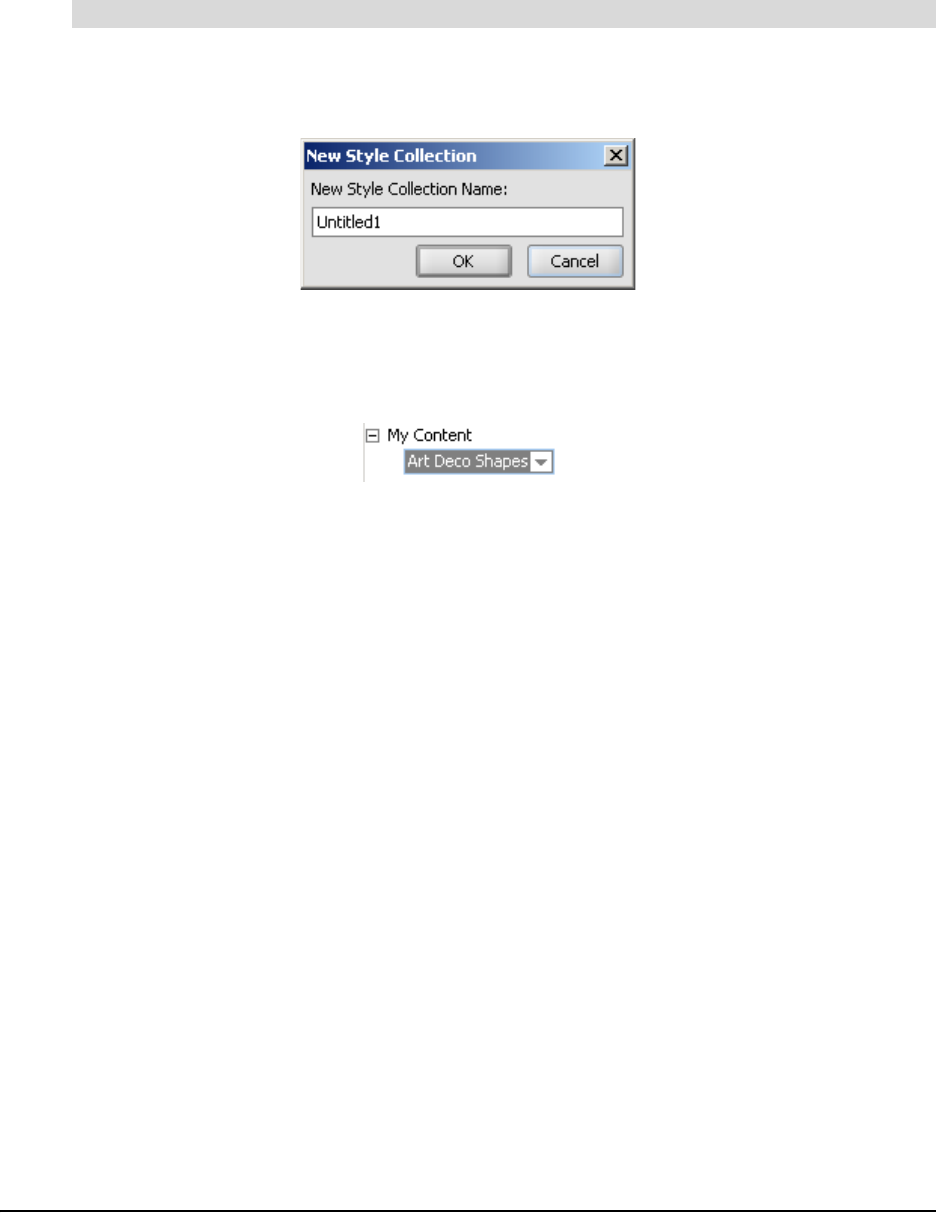
1. Select File > Content > New Style Collection.
The New Style Collection dialog box appears.
2. Enter the name of the new style collection file.
3. Click OK.
The new style collection appears in the My Content category on the Gallery toolbar.
4. Drag one or more symbols or connectors currently in the workspace onto the style palette.
OR
Right-click one or more symbols or connectors, and then select Add Style to Gallery.
OR
Select one or more symbols or connectors, and then select Tools > Add Style to Gallery.
NOTE: You may want to open other style collections to populate the workspace with the styles
you want to add to your custom style collection. If you prefer, use styles from other collections
as the starting point for creating unique styles (see Changing Symbol Appearance on page 33,
and Changing Connector Appearance on page 34).
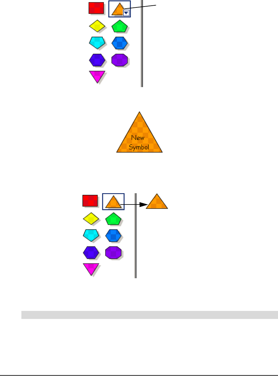
Adding Styles to Style Collections
You can freely add styles or styles that are already in other collections to your custom style
collections.
There are two ways to add styles:
• drag any symbol in the workspace directly onto the palette. The symbol can be one you’ve
modified yourself (see Changing Symbol Appearance on page 33, and Changing Connector
Appearance on page 34), or a symbol based on a style in another collection. You may first
want to open another style collection to populate the workspace with the styles you want to
add.
• import styles directly from other style collections (standard or custom)
A Favorites category is also available for those who prefer to quickly place all their favorite styles
into one catch-all category.
To create a custom style collection
28 Using Styles and Style Collections
1. Select the custom style collection to which you want to add styles on the Gallery toolbar.
2. Click, and then drag one or more symbols or connectors currently in the workspace onto the
style palette.
OR
Right-click one or more symbols or connectors, and then select Add Style to Gallery.
OR
Select one or more symbols or connectors, and then select Tools > Add Style to Gallery.
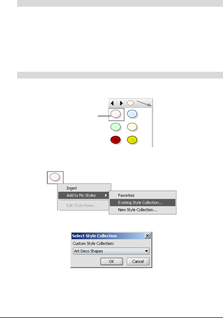
1. Select a style from any style collection in the Gallery style palette.
2. Click the drop-down arrow (or right-click), and then select Add to My Styles > Existing Style
Collection.
The Select Style Collection dialog box appears.
3. Click the drop-down arrow, and then select a style collection.
4. Click OK.
The style is added to the selected custom style collection.
To add a style to a custom style collection
To add a style to a custom style collection (importing from another collection)
Selected Style

Using Styles and Style Collections 29
1. Select a style collection on the Gallery toolbar.
2. Select a style from the style palette.
3. Click the drop-down arrow (or right-click), and then select Add to My Styles > Favorites.
Importing Style Collections
Many new style collections (and other SMART Ideas activities) are available at
www.education.smarttech.com, an online community for educators who use products from
SMART Technologies. This website contains hundreds of resources and helpful hints, especially
tailored for the unique needs of educators.
Select File > Content > Import Online Content.
The www.education.smarttech.com website opens at the SMART Ideas software activities
lessons page. Follow the instructions to download new style collections from this site.
Converting Style Collections
It’s easy to download new Ideas Style Collections (.ips) files from www.education.smarttech.com
(see the procedure above) or send them to and receive them from other users (see page 30).
After receiving a new .ips, your next task is to import it into the Gallery toolbar. Use the Open Style
Collection menu option to browse to and open the file. The .ips file appears as a style collection in
the My Content category of the Gallery toolbar. The new style collection reappears every time you
open the file, until you deliberately close the style collection. Closing a style collection removes it
completely from the Gallery toolbar.
All the custom style collections you create reside in My Documents\My SMART Ideas
Content\Collections, and you can browse to that location to copy the.ips files, and then send
them to others.
NOTE: You can’t import new style collections into any of the standard style collections in the
Symbols or Connectors categories. Neither can you close any of the standard style collections.
1. Select File > Content > Open Style Collection.
The Open dialog box appears.
2. Browse to the .ips file that you want to bring into the Gallery.
OR
Enter the name of the .ips file in the File name field.
3. Click the Open button.
To add a style to the Favorites category
To import online style collections
To import an .ips file into the Gallery
30 Using Styles and Style Collections
A new style collection appears at the bottom of the My Content category. When the style
collection is expanded, its styles appear in the Gallery style palette. The name of the style
collection is derived from the .ips file name.
1. On the Gallery toolbar, select the custom style collection you want to close under My Content.
2. Click the drop-down arrow, and then select Close.
The style collection disappears.
Saving Style Collections as .ips Files
In order to make a style collection available to others, you must first save it as an .ips file. You can
then e-mail it to other SMART Ideas software users or post it to a network location for the use of
others in your organization.
To use the .ips file as a style collection in SMART Ideas software, import it into the application, and
then open it as described above.
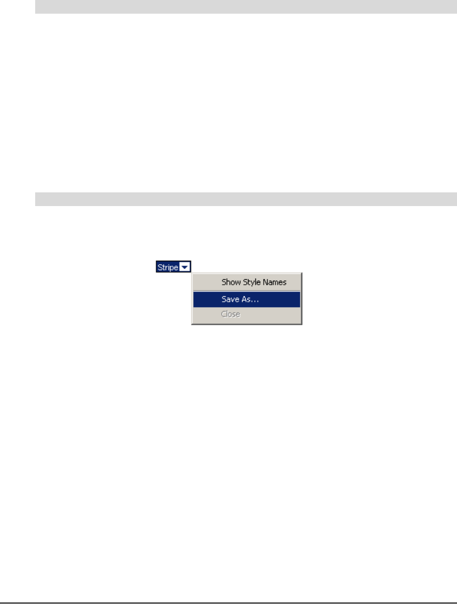
1. Select the style collection you want to save.
2. Click the drop-down arrow, and then select Save As.
A Save dialog box appears.
3. Browse to a folder in which you want to save the .ips file.
4. Click the Save button.
Showing and Editing Style Names
All the styles in the standard style collections come with descriptive text names that may, if you
choose, appear beside each style in the Gallery style palette.
If you like, you can name the styles that you either create or add to custom style collections. Unlike
the styles in standard style collections, you have the option of editing these names, should you
decide to rename them.
To remove a custom style collection from the Gallery
To save your style collection as an .ips file
Using Styles and Style Collections 31
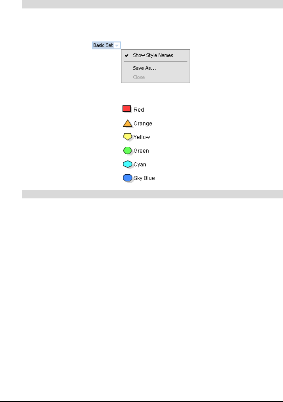
1. Select a style collection from the Gallery toolbar.
2. Click the drop-down button, and then select Show Style Names.
The styles in the Gallery style palette shrinks and their names appear beside them.
1. Select the style in the Gallery style palette.
2. Click the drop-down arrow, and then select Edit Style Name.
The style name appears in a text edit box, with a flashing insertion point.
3. Edit the style name, and then press ENTER.
To show style names
To edit a custom style name

32 Using Styles and Style Collections
Customizing Your Diagram 33
Customizing Your Diagram
In this section, you’ll learn how to make your diagrams more distinctive by:
• changing the appearance of symbols (this page)
• changing the appearance of connectors (page 34)
• adding two-color patterns and gradients to symbols (page 35)
• using StylePaint to copy an object’s formatting (page 36)
• adding a video file to a symbol (page 37)
• adding a sound file to a symbol (page 39)
• adding a note to a symbol (page 41)
• making a symbol transparent (page 42)
• adding a shadow to a symbol (page 43)
• using an imported image as a symbol (page 44)
• using clip art as a symbol (page 45)
• importing images into the clip art gallery (page 46)
• searching for clip art and cliplets (page 47)
• using interactive cliplets (page 48)
• inserting cliplets (page 49)
• grouping symbols with sticky symbols (page 50)
• adding a legend to your diagram (page 52)
• inserting a blank legend (page 53)
• creating a legend from a style collection (page 53)
• converting a legend to a custom style collection (page 54)
Changing the Appearance of Symbols
You can make your symbols plain and simple, or colorful and ornate. It’s easy to change the fill,
text or outline color of any symbol, as well as its shape and transparency. You can also give a
symbol a three-dimensional appearance by adding a shadow behind it.
TIP
To create a symbol style that you can use again and again, select the symbol, and
then select Tools > Add Style to Gallery. Your unique symbol is added to a
customized style collection for future use.
34 Customizing Your Diagram
1. Select one or more symbols.
2. To change the fill color, click the Fill Color arrow on the Formatting toolbar, and then select a
color from the palette, or click the More Colors button to access a larger color selection.
3. To change the outline color, click the Line Color arrow on the Formatting toolbar, and then
select a color from the palette, or click the More Colors button.
4. To change the shape, right-click, select Shape, and then select a shape from the list.
NOTE: To change a symbol’s text attributes, see Formatting Text on page 68.
Changing the Appearance of Connectors
You can modify a connector in much the same way as you modify a symbol. Previous sections
discussed linking symbols with connectors (page 7), labeling connectors (page 9), and using
styles to format connectors (page 24). This section focuses on changing the appearance of a
connector using the formatting toolbar.
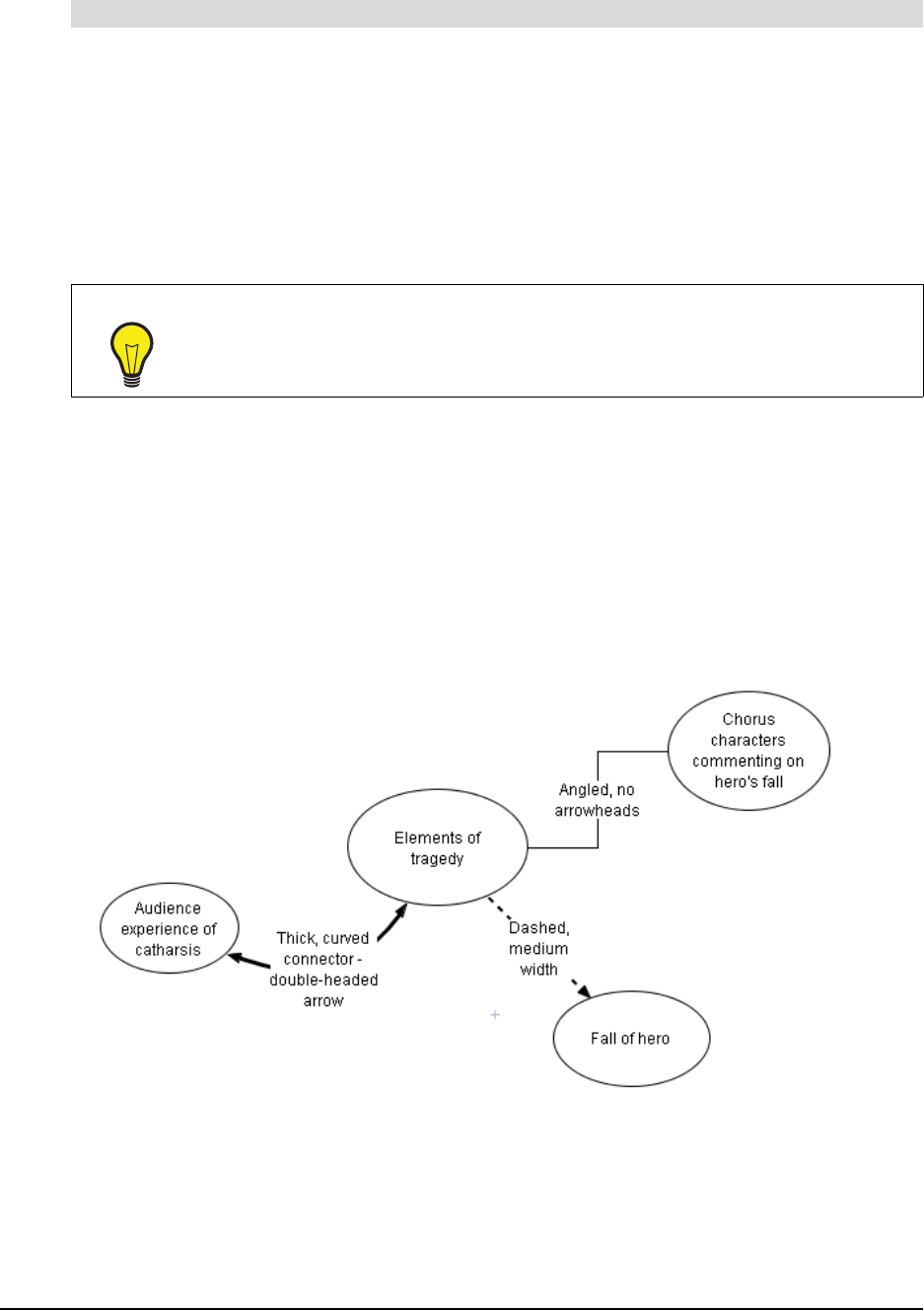
SMART Ideas software offers a wide range of connector shapes, types, colors, weights and ends
from which to choose. A connector can be straightforward, angled or graphically based. For
example, the following diagram uses three different connector styles.
To customize the fill, shape and outline of a symbol
TIP
Use StylePaint to transfer the formatting of a selected object to another object. See
page 36 for more information.
Customizing Your Diagram 35
1. Select one or more connectors.
2. To change the connector shape to angled, curved or straight, click the Select Connector
Type arrow on the Formatting toolbar, and then select one of the available connectors.
3. To change the connector line color, click the Line Color arrow on the Formatting toolbar, and
then select one of the available colors.
4. To change the connector ends to single, double, filled, transparent or no arrowheads, click the
Select Arrow Style arrow on the Formatting toolbar, and then select one of the available
arrow styles.
5. To use an image-based connector, click the Deluxe Connector arrow on the Formatting
toolbar, and then select one of the available deluxe connectors.
6. To change the color of an image-based connector, click the Fill Color arrow on the Formatting
toolbar, and then select one of the available colors.
NOTE: To customize connector labels, see Formatting Text on page 68.
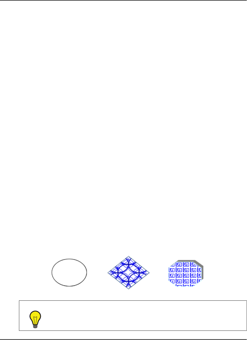
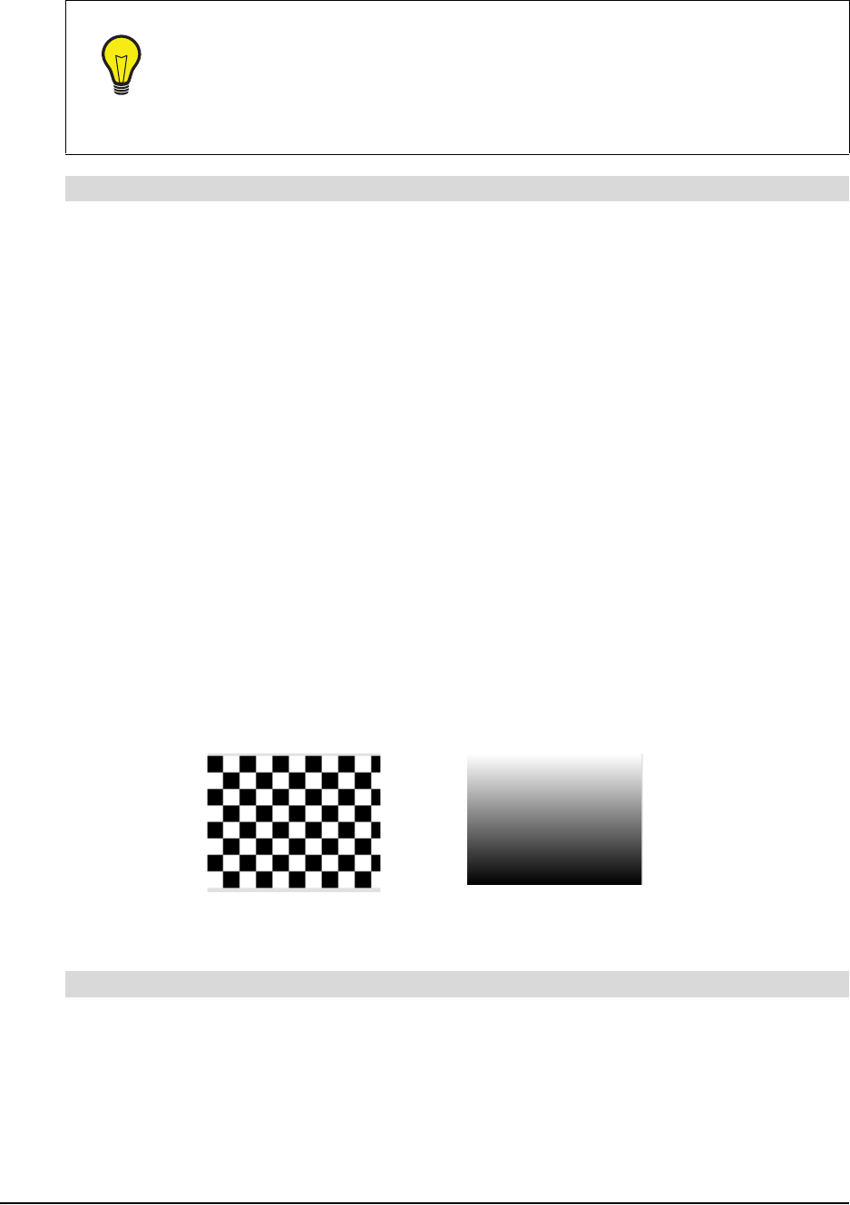
Adding Two-Color Patterns and Gradients to Symbol Fills
Your symbols can have a uniform, single-color fill, a two-color patterned fill or a two-color gradient
fill. The patterned fills are regularly recurring symmetrical objects that create a tiled appearance,
similar to wallpaper. The gradient fills display a progression between two colors along either a
vertical, diagonal or horizontal path.
1. Select a symbol(s).
2. Click the Fill Color arrow on the Formatting toolbar, and then select Fill Effects.
TIP
To create a connector style that can be used again and again, import your
connector into a customized style collection on the Gallery toolbar. Open the style
collection, and then click and drag your unique connector into the palette section of
the Gallery toolbar.
For more information on creating and using styles, see Formatting Connectors with
Styles on page 24.
To customize a connector
A Two-Color Pattern A Vertical Gradient Fill
To add a two-color pattern or gradient to the symbol fill
36 Customizing Your Diagram
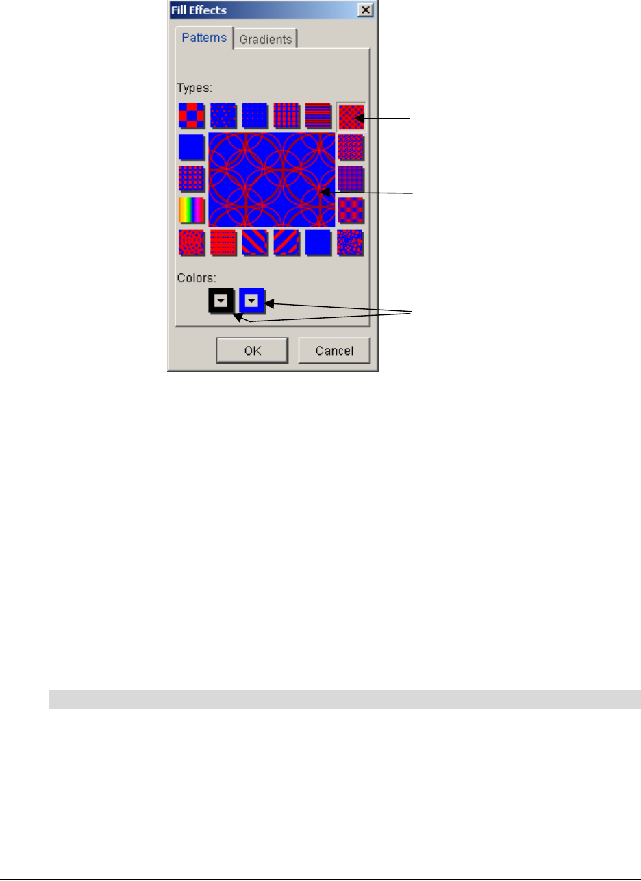
The Fill Effects dialog box appears.
3. To add a pattern to the symbol, click one of the pattern types.
OR
To add a gradient to the pattern, click the Gradients tab, and then click one of the gradient
types.
4. To select the two colors that make up the pattern or the gradient:
a. Click the first Colors button, and then select one of the available colors.
b. Click the second Colors button, and then select one of the available colors.
5. Click OK.
Using StylePaint to Copy an Object’s Formatting
After you’ve changed a symbol's appearance to make it look the way you want, you can easily
transfer that symbol's formatting to other symbols using StylePaint. You can do the same with any
connector in the workspace.
1. Select the object that has the formatting you want to copy to another object.
2. Click the StylePaint button on the Standard toolbar.
The pointer turns into a paint brush.
3. Click the object to which you want to copy the original object’s formatting.
4. When you finish copying the original object's formatting, click the StylePaint button again.
To copy one object’s formatting to another object
Click a
p
attern type
Preview of
Pattern and
Colors
Click to sele
c
the two colo
r
for the patte
r
Customizing Your Diagram 37
Adding a Video File to a Symbol
Make your concept map come alive by integrating a video file with your diagram. You can show the
video in a larger, full screen format, scroll to any position in the video and adjust the volume.
You can import any of the following video file formats: .wmv, .avi, .aiff, .mpeg and .mov.
1. Select a symbol to which you want to add a video.
OR
Click in the workspace where you want to add a video.
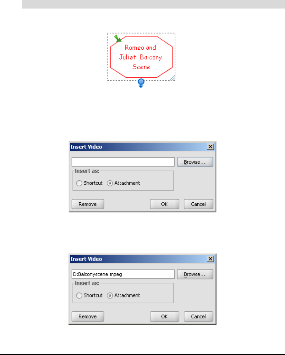
2. Select Insert > Video.
The Insert Video dialog box appears.
3. Click the Browse button, and then navigate to the video file you want to add.
4. Select the file, and then click the Open button.
The Insert Video dialog box reappears.
To add a video to a symbol
38 Customizing Your Diagram
5. Click Shortcut if you don’t want to increase the size of the current SMART Ideas file.
Otherwise the video file is added to the current file as an attachment, and increases its size
accordingly.
NOTE: If you insert a shortcut rather than an attachment, ensure that the file is accessible
when you want to show it.
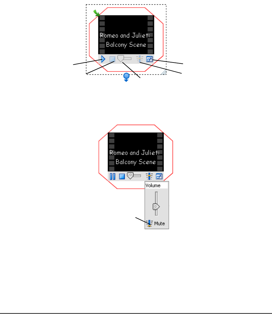
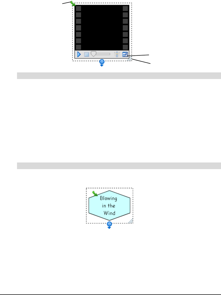
6. Click the OK button.
The symbol text appears in white over a black video icon. A video toolbar also appears to let
you play the video and adjust various settings.
Notes on Playing Videos
You can mute the sound on a video. Click the Volume button, and then click the small Mute button
near the bottom of the sound slider.
You can jump ahead or back in a video by clicking and dragging the Video Position slider.
Try playing the video in Full Screen mode so a large group can see it more easily. Press the Full
Screen button in the lower-right corner. The video appears in a much larger format and all
potential distractions—like menus and toolbars—are removed. You can enlarge even further by
clicking the Maximize button. However, the picture quality for this result may be grainy. To return to
normal view, press the green arrow button in the upper-left corner.
Play
Pause
Volume
Full Screen
Video Position Slider
Click to mute
the sound
Customizing Your Diagram 39
You can also enlarge the video symbol. Click and drag the Resize button to enlarge the symbol for
better viewing.
1. Select the symbol.
2. Select Insert > Video.
The Insert Video dialog box appears.
3. Click the Remove button.
Adding a Sound File to a Symbol
Add sound to your concept map and you’ll be sure to capture the interest of even the most
inattentive student. You can add a sound file to an existing symbol or add it to the concept map.
Import any of the following sound file formats: .wav, .aiff, .rmf, .mid and .au.
1. Select a symbol to which you want to add a sound file.
OR
Click in the workspace where you want to add a sound file.
2. Select Insert > Sound.
The Insert Sound dialog box appears.
3. Click the Browse button, and then navigate to the sound file you want to add.
4. Select the file, and then click the Open button.
To remove a video from a symbol
To add a sound file to a symbol
Resize button
Full Screen button
Restore size
40 Customizing Your Diagram
The Insert Sound dialog box reappears.
5. Click Shortcut if you don’t want to increase the size of the current SMART Ideas file.
Otherwise the sound file is added to the current file as an attachment, and increases its size
accordingly.
NOTE: If you insert a shortcut rather than an attachment, ensure that the file is accessible
when you want to play it.
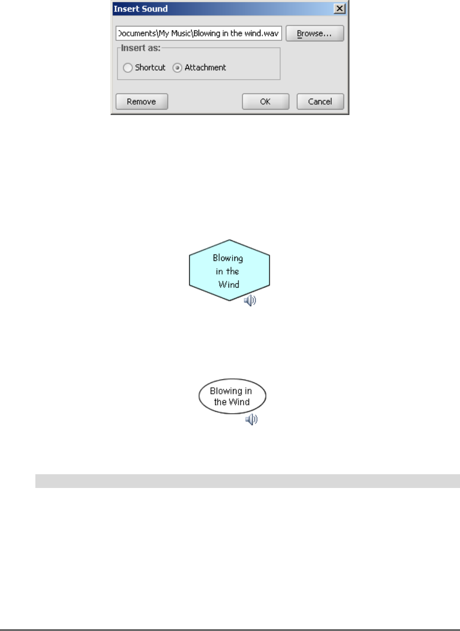
6. Click the OK button.
7. If a symbol was initially selected, it appears with a speaker icon.
OR
If no symbol was selected, the file name of the sound file appears inside a round, unfilled
symbol with an accompanying speaker icon.
8. Hover over or click the speaker icon to play the sound file.
9. Move off the speaker icon or click again to stop the sound file.
1. Select the symbol.
2. Select Insert > Sound.
The Insert Sound dialog box appears.
3. Click the Remove button.
To remove a sound file from a symbol
Customizing Your Diagram 41
Adding a Note to a Symbol
If you want to add a few lines of explanation, reference a source or add a few lines of commentary
to a symbol, add a note. When you do this, a Note icon appears on the symbol (even when it’s not
selected).
When you hover your mouse over the Note icon, you’ll see the entire contents of the note. And it’s
easy to change or add more text to a note: Move your mouse pointer over the Note icon, and then
click to access a fully editable text box.
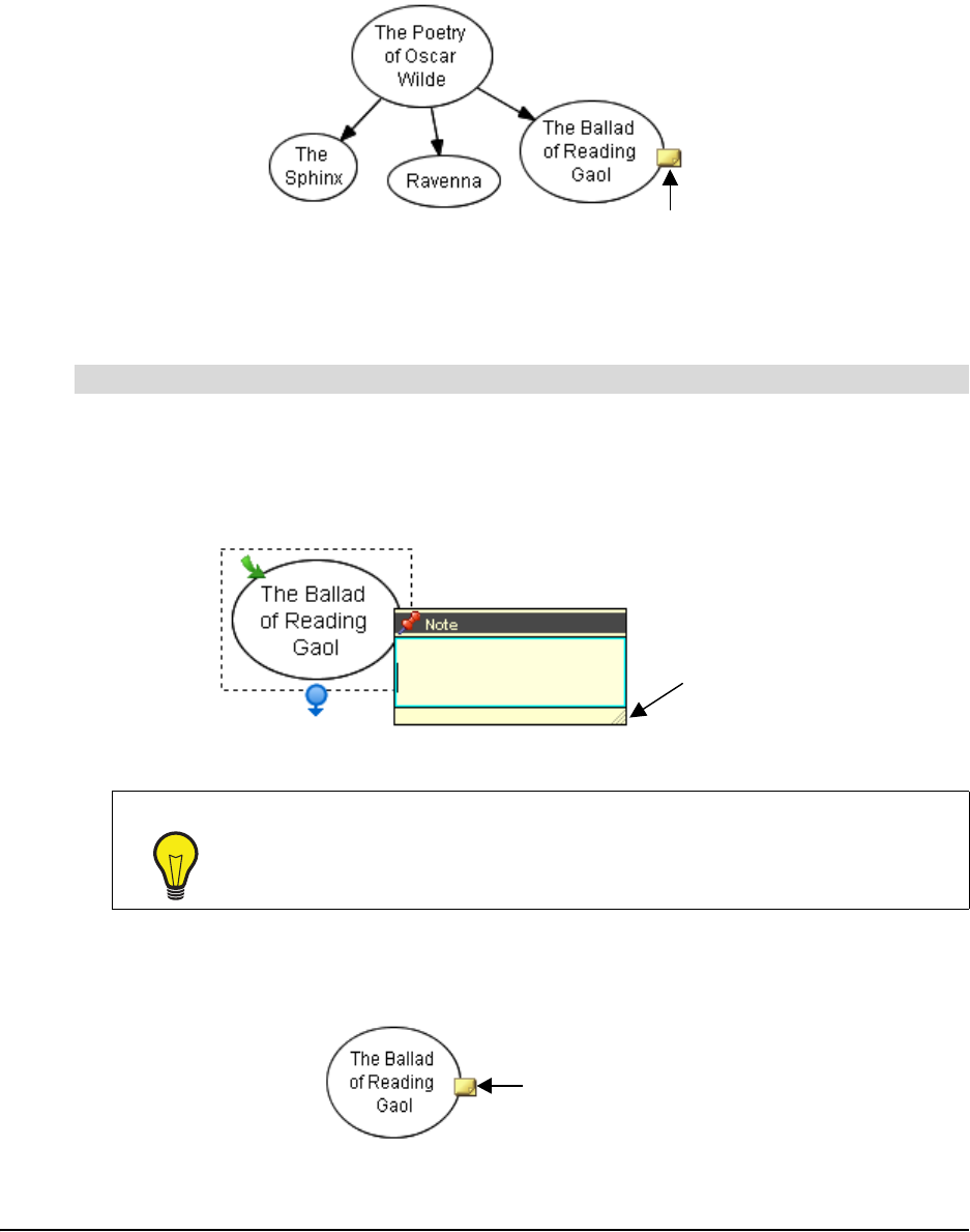
1. Select the symbol.
2. Click the Note button on the Formatting toolbar.
A text box appears next to the selected symbol.
3. Type a note.
4. Click once outside of the text box.
A Note icon appears on the symbol.
To add a note to a symbol
TIP
If you’re writing a long note, you may need to resize the text box for optimal
visibility. Drag the Resize handle in the bottom right corner of the text box after
you’ve entered the note text.
Note Icon
Resize
Handle
Note Icon
42 Customizing Your Diagram
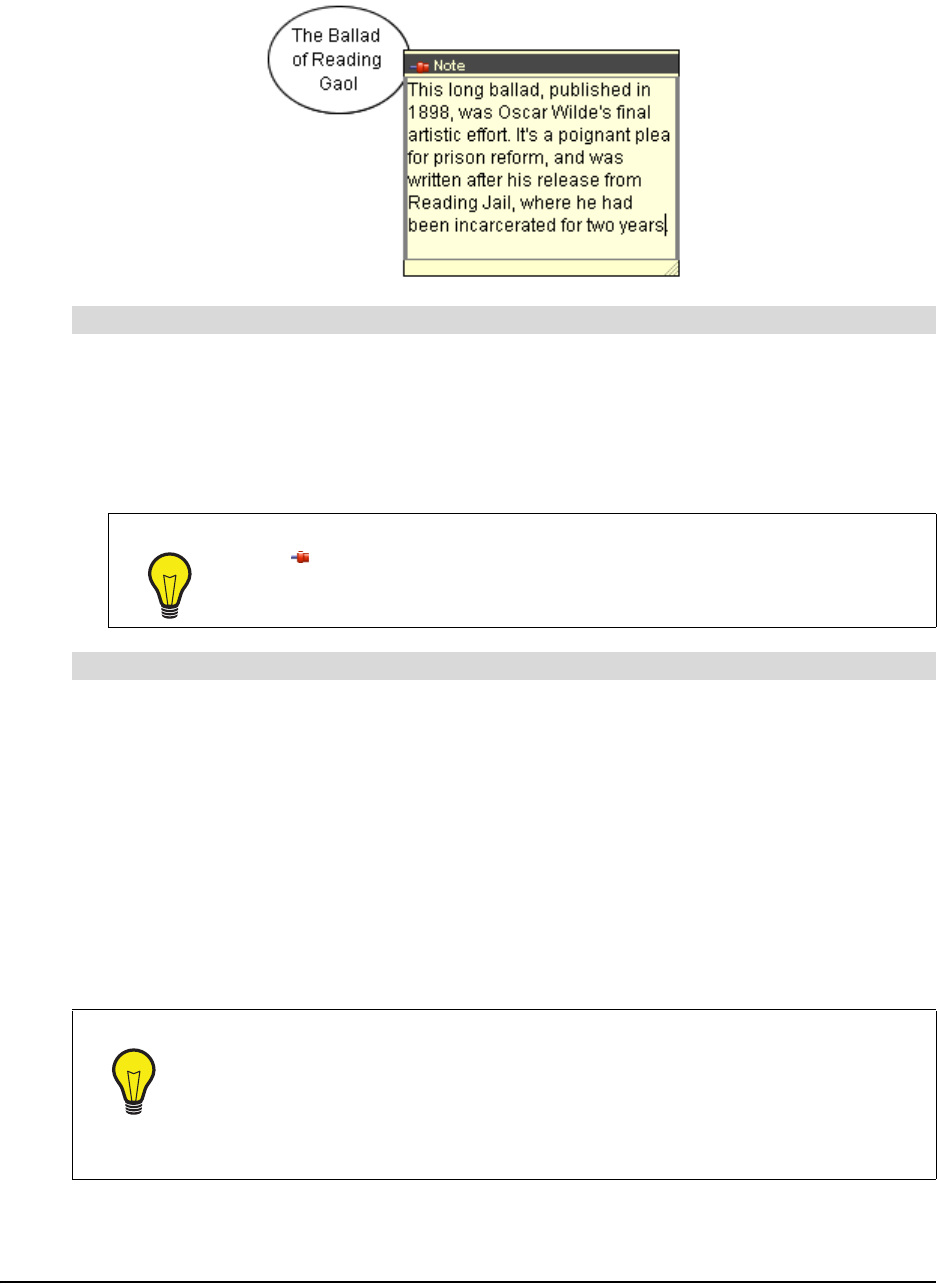
5. Move your mouse pointer over the Note icon to view the note text.
1. Click the Note icon.
The note contents appear inside a text box.
2. Add or change the text as you prefer.
Click once outside of the text box to commit the text.
1. Select the symbol that contains the note you want to delete.
2. Select Edit > Delete Note.
OR
Right-click on the note, and then select Delete Note.
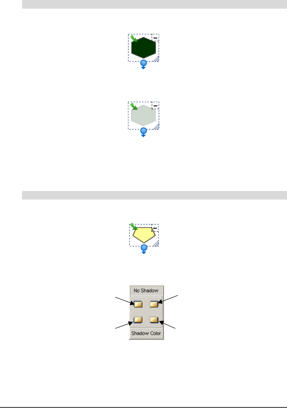
Making a Symbol Transparent
In SMART Ideas software, you can make a filled symbol 25%, 50%, 75% or 90% transparent—a
range of transparency that lets you make a symbol only a little more transparent than other
diagram objects, or so faint it’s nearly invisible.
To edit a note
TIPS
• To make a note stay visible even when the pointer isn't over it, click the
pin in the upper-left corner.
• To change the color of a note, right-click it, and then select a color.
To delete a note
TIPS
• You can use the degree of transparency to reflect the relative importance of the
ideas or facts your symbols may represent. You can also use it to show temporal
relationships, giving older events in a timeline a more faded appearance than
recent events.
• You can make overlapping objects transparent so they don’t obscure the
underlying objects in your diagram.
Customizing Your Diagram 43
1. Select a filled symbol.
2. Select Symbol > Transparency, and then select a degree of transparency.
The transparency for the selected symbol changes accordingly.
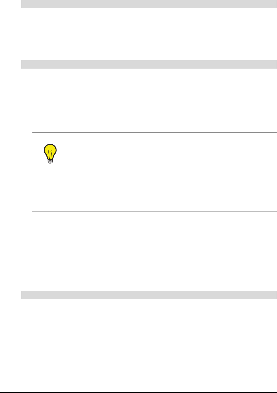
Adding a Shadow to a Symbol
Give your diagram the appearance of depth by adding shadows to your symbols. You can use the
default gray color or select any other color. Note that you must also specify the corner of the
symbol in which you want the shadow placed.
1. Select a symbol.
2. Select Symbol > Shadow.
3. Click a Shadow Direction button to select the corner that the shadow occupies.
To make a symbol transparent
To add a shadow to a symbol
Upper-Left
Corner
Upper-Right
Corner
Lower-Right
Corner
Lower-Left
Corner

44 Customizing Your Diagram
The selected symbol appears with a gray shadow.
1. Select a symbol.
2. Select Symbol > Shadow > Shadow Color.
The Shadow Color dialog box appears.
3. Select a color, and then click OK.
The selected symbol appears with a colored shadow in the last corner specified.
NOTE: The next time you create a shadow, the default shadow color (gray) is restored.
Using an Imported Image as a Symbol
You can add visual appeal to any diagram by importing a .bmp, .jpg, .jpeg, .gif, .png, .svg, .ico or
.wmf image file and using it as a symbol. You can then connect that symbol to other symbols in a
diagram, and then customize it as you would any other symbol.
For example, you can use public-domain photographs. Such an image makes a more memorable
symbol than simply enclosing a word in a shape (although you can integrate that word into the
symbol as well).
1. Select one or more symbols.
2. Select Insert > Image from File.
An Open dialog box appears.
3. Browse to the image file you want to import into the diagram.
NOTE: You can import .bmp, .jpg, .jpeg, .gif, .png, .svg, .ico and .wmf files.
4. Click the Open button.
To add a colored shadow to a symbol
To use an imported image as a symbol
TIPS
• Many works of art (excluding most mid-to-late 20th century works) are now
in the public domain. Thousands of Internet sits (including national art
gallery sites) allow reproductions of their materials for the purpose of
scholarship and teaching.
• You can use a screen capture tool (such as the Screen Capture tool in
Notebook™ software) and your Web browser to surf the Internet, and then
capture images from fine art, literary, historical or scientific sites to integrate
into your diagrams.
Customizing Your Diagram 45
1. Double-click the image symbol.
A text box appears.
2. Type the text label.
3. Press the ENTER key on your keyboard.
1. Select the symbol with an image you want to remove.
2. Select Edit > Remove Picture.
OR
Right-click, and then select Remove Picture.
The image contained within the symbol disappears.
Using Clip Art as a Symbol
You can add visual appeal and interest to your diagrams using the collection of clip art images that
comes with SMART Ideas software. Clip art images are stored on the Gallery toolbar, and you can
drag and drop them into the workspace as you would with styles in style collections.
When you add a clip art image to a diagram, it becomes a symbol you can treat like any other
symbol. You can surround the image with symbol shapes, resize it, connect it to other symbols,
and then add text to it.
1. Click the drop-down arrow at the top of the Gallery toolbar, and then select Clip Art Gallery.
2. Browse through the categories. When you select a category, all the clip art associated with it is
displayed in the palette area below.
3. Click and drag a clip art image into the workspace.
OR
Click again on the image.
To add a text label to the image symbol
To remove an image from a symbol
TIPS
You can make your image symbols as elaborate or as simple as you like:
• You can change the frame around the image by changing the symbol shape.
Right-click the symbol, and then select a different shape.
• You can create a colorful matte effect around your symbol. Right-click the
image symbol, select Fill Color, and then select a color or fill effect.
• If you like, dispense with the frame altogether by selecting a shape that’s
identical to the image shape. For example, with a rectangular image, right-
click the symbol, and then select Shape > Rectangle. The frame inside the
symbol disappears.
To use clip art as a symbol
46 Customizing Your Diagram
4. If the clip art appears smaller than you’d like, click and drag the Resize button to enlarge it.
While it’s enlarging, the image may appear unclear, but a high resolution image is restored
when you finish dragging the image.
5. To frame the clip art image with a shape, click the drop-down arrow at the top of the Gallery
toolbar and select Style Collections, select a symbol from the Style palette, and then click on
the clip art.
Importing Images into the Clip Art Gallery
You can integrate your favorite images into your diagrams by importing your own image collections
into the clip art gallery. You can import any .jpg, .gif, .png, .bmp, .ico, .wmp or .svg file into the
gallery.
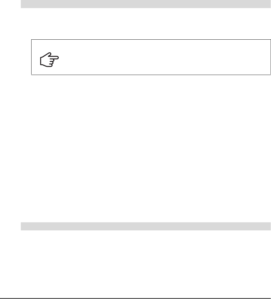
You can create your own Clip Art category first, and then add clip art to it, or create the new
category at the same time as you import the clip art.
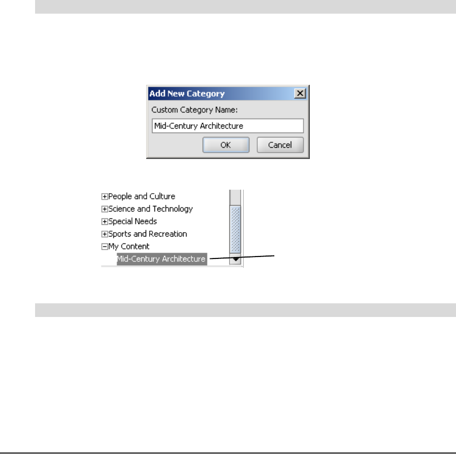
1. Select File > Content > New Clip Art Category.
The Add New Category dialog box appears.
2. Enter a name in the Custom Category Name box.
3. Click OK.
Your new Clip Art category is stored in My Documents\My SMART Ideas Content\Clip Art.
1. Click the drop-down arrow at the top of Gallery toolbar, and then select Clip Art Gallery.
2. On the Gallery Toolbar, select My Content.
3. Click the Add Clip Art link in the Style palette.
OR
If the Style palette does not contain the Add Clip Art link, right-click the palette, and then select
Add Clip Art.
To create a custom Clip Art category
To add clip art to a custom Clip Art Category
Your New Clip Art
Category
Customizing Your Diagram 47
The Open dialog box appears.
4. Browse to and select the clip art image you'd like to add.
The Select Category dialog box appears.
5. Click the Custom Categories arrow, and then select a category for the image(s).
OR
Click the New Category button to create a new category for the image(s).
6. Click OK.
The Clip Art Style palette displays the selected image(s).
1. Select Help > Download More Clip Art.
2. Follow the instructions on downloading and installing the selected clip art collection.
Searching for Clip Art and Cliplets
The clip art and cliplet gallery provided with SMART Ideas software contains scores of images
organized into such subject categories as social studies, language arts, math and science. You
can add as many of your own images as you like, resulting in a potentially vast collection of
images.
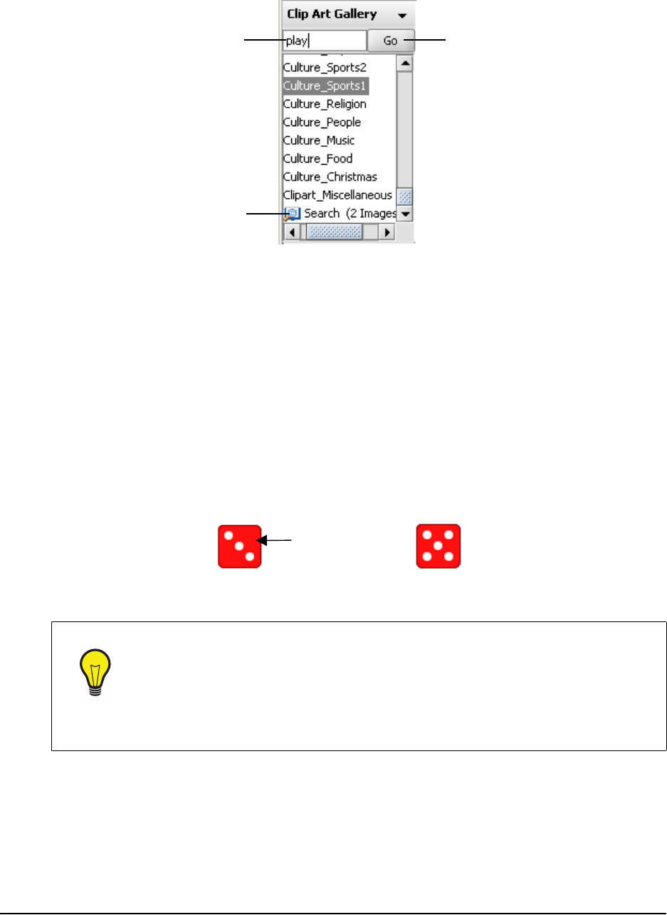
We’ve provided a search engine so you can easily find the right image. Enter a search term and
the Gallery searches by filename for matches. If any part of the image filename matches the
search term, it appears in the search results. For example, if you enter "ball" as a search term,
among the search results you’ll find clip art entitled "ball", "ballet" and "balloon."
NOTES:
• You can view the filenames for the .wmf clip art files that comes with SMART Ideas software
by hovering the pointer over the images in the palette.
• Any image files you import are searched by the first part of their filenames (the file extension
isn’t necessary). For example, if you import a file called Byron.jpg, enter the keyword “Byron”
to find the associated image in the clip art gallery.
1. Select Clip Art Gallery or Cliplet Gallery from the Gallery drop-down arrow.
2. Enter a search term in the text entry box.
To import more free clip art from SMART Technologies
IMPORTANT
• Ensure all instances of SMART Ideas software are closed before performing
a download.
• Save the clip art collection to your computer before installing it. Opening it
directly from the website may result in errors.
To search the Gallery by search term
48 Customizing Your Diagram
3. Click the Go button.
The results of the search appears in the palette area of the Gallery.
Using Interactive Cliplets
Cliplets are an animated form of clip art that you can insert into the workspace and interact with to
accomplish many teaching objectives. The cliplets provided with SMART Ideas software help you
teach geometry, clock reading, metric/imperial measurements and basic arithmetic principles.The
cliplets include timers, a pair of dice, teaching clocks, actual working clocks, and a fully functioning
calculator. The dice, for example, can be used like regular dice. Instead of rolling the dice,
however, you click on the image of the dice, and the number of dots changes randomly. Similarly,
you can drag the arms of the transparent protractor cliplet to measure an angle, or press the
buttons in the calculator cliplet to solve a math problem.
TIP
If you’re working on a classroom SMART Board interactive whiteboard, use the
timer cliplet when your students are writing a timed in-class assignment or a test.
1. Click the Maximize button and the timer fills the screen.
2. Drag the arrow to set the timer: the time remaining is shaded a bright red. This
red shading disappears as the time passes and your students are able to see
at a glance how much time remains.
Enter search term here...
...then click Go
Search Results
Click anywhere
on the image to
“roll” the dice
Before Click
A
fter Click
Customizing Your Diagram 49
Inserting Cliplets
Once you insert a cliplet, you can click, drag or otherwise manipulate components of the image to
fulfill the purpose of the cliplet.
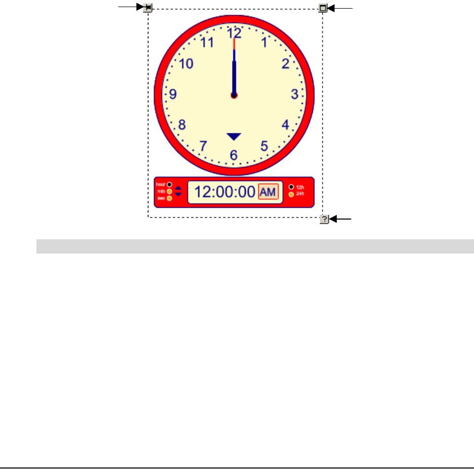
Most cliplets are easier to use if you lock them into place first. Otherwise, you may move the entire
cliplet rather than the functional part of the cliplet, such as the protractor arm. To lock cliplets in
place, click the Tack button in the upper-left corner of the selected cliplet. Also, you can access
Help for those cliplets with complicated functionality by clicking the Help button in the lower-right
corner of the selection rectangle.
Some cliplets, such as the timers and clocks, also feature a Maximize button in the upper-right
corner of the selection rectangle. The Maximize button enlarges the cliplet so that it takes up the
entire screen. You can then use a clock cliplet with a much larger face for teaching time-telling, or
set the timer for in-class tests, and then maximize it so it can be viewed more easily by the entire
class.
1. Select Insert > Cliplet.
A list of cliplet categories appears in the top pane of the Gallery.
2. Select a cliplet category.
Cliplet images associated with that category appear in the palette.
3. Click and drag a cliplet onto the workspace.
OR
Right-click, and then select Insert.
4. To tack the cliplet in place, click the Tack button in the upper-left corner of the selection
rectangle.
To insert a cliplet
Click to lock
the cliplet in
p
lace
Click for Help
Click to
maximize to
full-screen
size
50 Customizing Your Diagram
NOTE: Not all cliplets can be maximized. However, all the time-related cliplets (clocks) can be
maximized.
1. Select a cliplet.
2. Click the Maximize button in the upper-right corner of the selection rectangle.
The cliplet enlarges to take up the entire screen.
3. To return to normal size, press the Back button in the upper-left corner of the screen.
OR
Press any key on the keyboard.
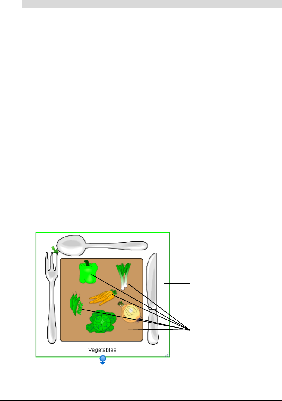
Grouping Symbols with Sticky Symbols
Help younger students develop their sorting and classification skills with sticky symbols. You can
designate one or more symbols in the workspace as a "sticky symbol"—i.e., a symbol that is, in
effect, sticky. When you move another symbol onto it, that symbol clings to the sticky symbol. In
effect, a sticky symbol contains any symbols moved onto it as a group. Each symbol you drag onto
the sticky symbol becomes a part of the group, which you can then move around the workspace as
one collective object.
To move the group, click on the sticky symbol and then drag. If you click on one of the individual
symbols inside the sticky symbol, you’ll select that symbol (rather than the group).
For example, you could designate a symbol that represents an empty plate as a sticky symbol,
and then move clip art symbols of various food items onto the empty plate. The plate and the food
symbols it contains are now an object group that you can move anywhere in the workspace as a
single unit.
To maximize a cliplet (and then restore it to normal size)
Sticky Symbol
Individual Symbols
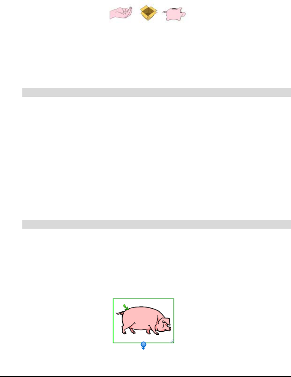
Customizing Your Diagram 51
SMART Ideas software comes with several ready-made sticky symbols, including an open box, a
piggy bank and a cupped hand. You can find these sticky symbols by clicking the Stickies arrow
button on the Standard toolbar. To see even more sticky symbols, select More Sticky Symbols
from the same drop-down list, and an entire sticky style collection appears on the Gallery toolbar.
However, it’s also easy to turn any symbol you like—a symbol from an existing style collection or a
symbol you’ve created in the workspace—into a sticky symbol.
NOTE: The symbols you drag onto a sticky symbol are not affected by any change in the color,
size or shape of the sticky symbol.
1. Click the Stickies arrow on the Standard toolbar, and then select a sticky symbol from the list.
The new Sticky symbol appears in the workspace.
OR
Select Tools > Stickies > More Sticky Symbols.
A Stickies category appears in the style collections on the Gallery toolbar. In the Style palette,
drag and drop or double-click a Sticky symbol to add it to the workspace.
2. Click and drag one or more symbols onto the sticky symbol.
Each time you drag a symbol onto the sticky symbol it appears outlined in blue.
3. Click and drag the sticky symbol to move the entire group around the workspace. If you click
and drag individual symbols, you’ll move them off the sticky symbol, and they are no longer a
part of the "sticky" group.
1. Select a symbol in the workspace.
2. Click the Stickies arrow on the Standard toolbar, and then select Create Sticky Symbol.
OR
Select Tools > Stickies > Create Sticky Symbol.
The symbol appears surrounded by a solid green selection rectangle.
3. Click and drag other symbols onto the sticky symbol you created.
To group a collection of symbols with a sticky symbol
To create a sticky symbol
Some SMART Ideas Sticky Symbols
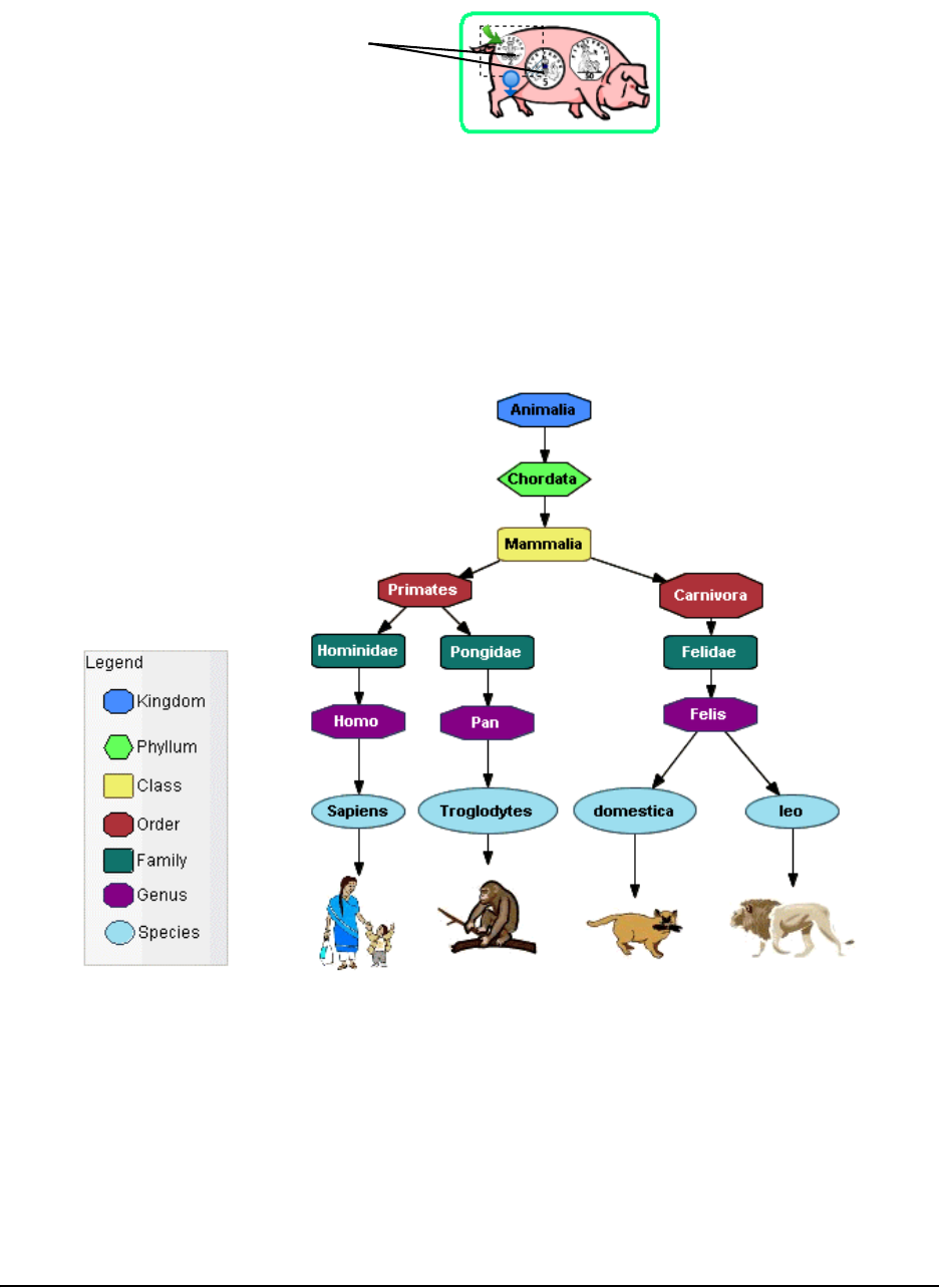
52 Customizing Your Diagram
4. Each time you drag a symbol onto the sticky symbol, it reappears outlined in green.
5. Click and drag the sticky symbol to move the group of symbols. If you click and drag individual
symbols, you’ll move them off the sticky symbol.
Adding a Legend to Your Diagram
A legend is an explanatory list of some or all of the symbols used in a SMART Ideas diagram. A
legend lets you assign an additional meaning to your symbols based on their shape and color, so
that, in effect, you create a key to your diagram, as shown in the example below.
The explanatory text beside each symbol comes from the text label associated with that symbol.
So, before dragging a symbol onto the legend, you may want to add or change that text so it
serves as explanatory text.
After you've created the legend, you can save it for later use by converting it into a custom style
collection. When you want to use the legend again, select that style collection and use it as the
basis for another legend.
Individual
Symbols

Customizing Your Diagram 53
NOTES:
• If the legend is too big or too small after you've added all the symbols, you can easily resize it,
as you would any other symbol.
• Symbols you add to the legend are grouped with it automatically. When you move the legend,
the symbols it contains move with it.
You can create a legend by:
• inserting a blank legend and adding the symbols manually
• creating a legend from the current style collection
• using a style collection as a legend
Inserting a Blank Legend
When you insert a blank legend in the workspace, you must then add the symbols to it manually.
This is especially useful if you want to create a legend that contains only a few symbols.
1. Select Insert > Legend > Blank.
A blank legend appears in the workspace.
2. Select a symbol in the workspace that you want to use as part of the legend. Add explanatory
text to the symbol, or modify existing text so it serves that purpose.
3. Drag the symbol into the legend.
The symbol becomes part of the legend: The symbol text becomes its title, and the title
automatically appears to the right of the symbol.
4. Repeat this process for as many symbols as you'd like.
Creating a Legend from a Style Collection
You can create a legend automatically from the currently selected style collection. It’s important to
note, however, that you can’t select specific styles in this case; the entire collection of styles
becomes the basis for the workspace legend.
Also, the explanatory text for each symbol is derived from the style names as they appear in the
palette. Therefore, you may want to alter the style names before creating the legend.
To insert a blank legend
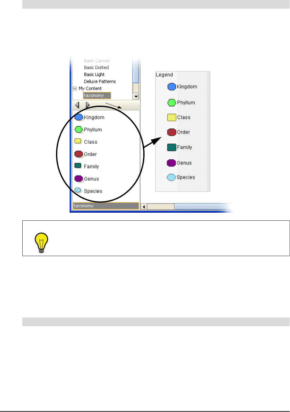
54 Customizing Your Diagram
1. On the Gallery toolbar, select the style collection you'd like to use as the basis for the legend.
2. Select Insert > Legend > Current Style Collection. The legend appears in the workspace.
Every symbol style in the style collection becomes a part of the legend, and the legend’s
explanatory text is derived from the style names.
Converting a Legend to a Custom Style Collection
Once you've created a legend, you can convert it to a new style collection or add it to an existing
custom style collection for later use. When you convert a legend to a custom style collection,
SMART Ideas software automatically saves it to your computer's My Documents\MY SMART
Ideas Contents\Collections folder as an .ipr file.
1. Right-click the legend, and then select Add Legend to Gallery.
NOTE: Be sure to right-click the legend and not one of the symbols it contains.
2. Click the New Style Collection button to create and name the new collection.
OR
Select a custom style collection to which you'd like to add the legend.
3. Click OK.
To create a legend from a style collection
TIP
Many of the style collections included with SMART Ideas software use style names
that describe a symbol's appearance rather than its meaning. Rename the symbols
with more meaningful names before you use a collection as a basis for the legend.
To convert a legend to a custom style collection
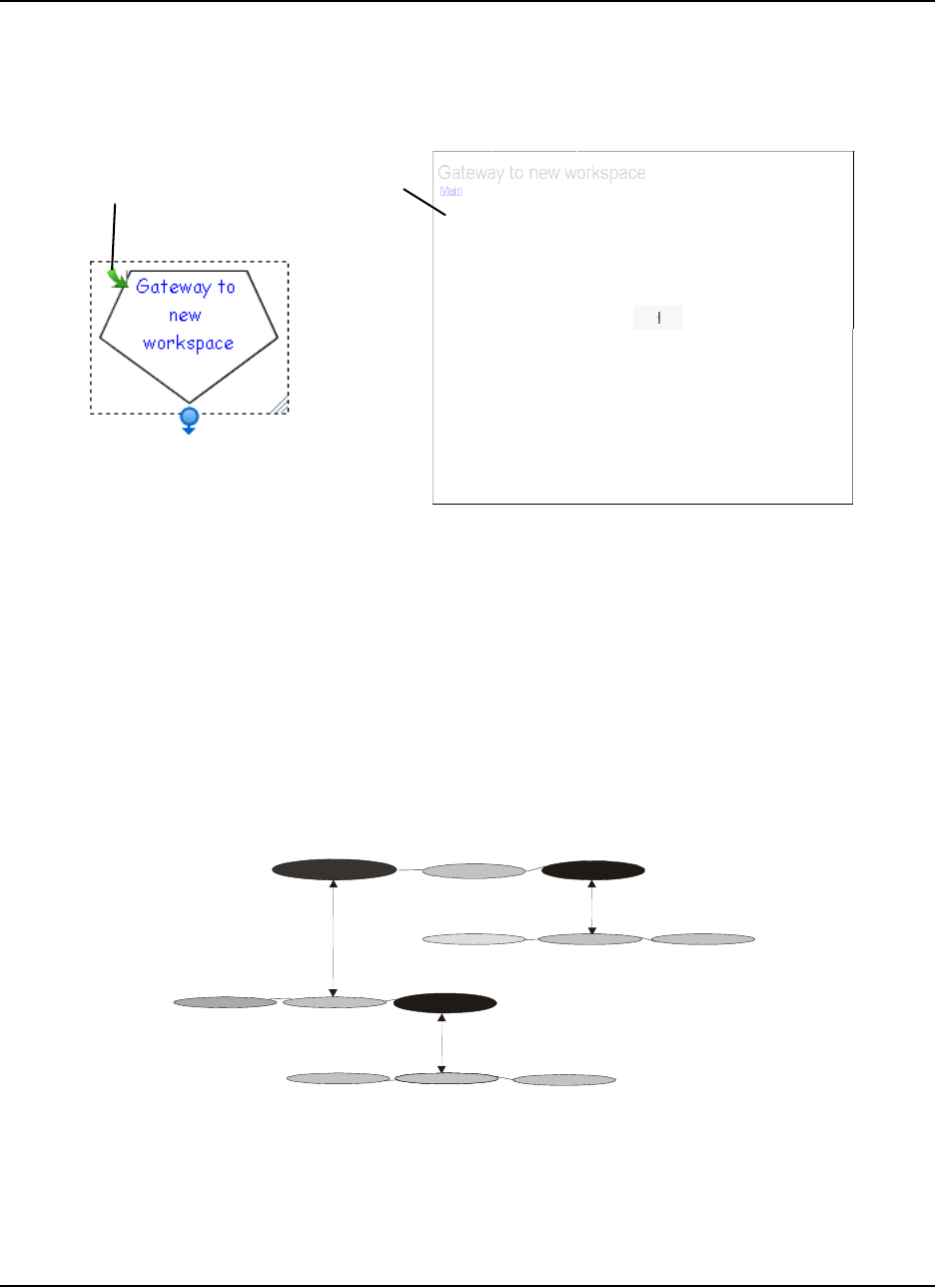
Getting to Know the Workspace 55
Getting to Know the Workspace
What do you do if you want a fresh, blank workspace to add additional information to your current
diagram? Click the sub-level icon of any symbol in the current workspace and a new, blank sub-
level workspace opens.
Sub-Level Workspaces
With SMART Ideas software, you can give your diagrams the added dimension of workspace
depth. Every symbol in the current workspace is a potential portal to another workspace on which
you can add another symbol, an image or a fully connected diagram of many symbols and images.
Likewise, every symbol in your new sub-level workspace is the potential source of another unique
workspace. Although there is no real limit to the number of symbol sub-levels you create, the
amount of information in your diagrams effects the size of the SMART Ideas file.
The following figure depicts three symbols and their accompanying sub-levels in cross section:
symbols on the main level (symbols 1 and 2) have associated sub-levels, and one symbol on a
sub-level (symbol 3) has its own sub-level.
Click here...
...for this result
(a new, blank
workspace)
Main Level
1
Symbol 1
Sub-Level
2
Symbol 2
Sub-Level
2
3
Symbol 3 Sub-Level
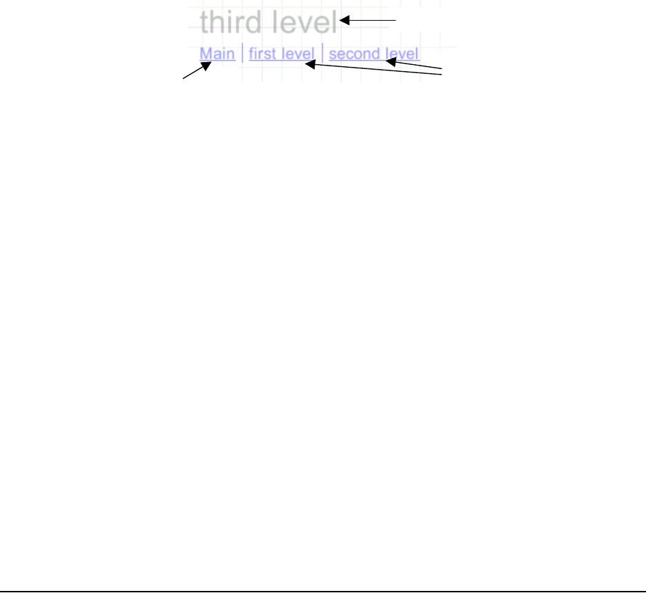
56 Getting to Know the Workspace
Tools for Navigating in Your Sub-Level Workspaces
It’s easy to keep track of where you currently are in relation to other sub-levels using any of the
features described below.
Using the Back Button
After you’ve used a sub-level workspace, you can return to the level of the originating symbol by
clicking the Back button on the Standard toolbar.
Using the Watermark Links
If you’ve created many sub-levels, you’ll want to use the sub-level watermarks in the upper-left
corner of each level to stay oriented. This watermark appears by default and is derived from the
originating symbol text for the current level, as well as the originating symbol text from all other
related sub-levels.
Click on the different links in the watermark to return to the original workspace level (called Main)
or to the other sub-levels.
Although watermark links appear by default, you can easily hide the watermarks to reduce
workspace clutter. To hide watermarks, clear the selection of View > Watermark.
Using the Navigator in the Gallery Toolbar
The Navigator is a sidebar that allows you to easily navigate when you’re working with multiple
levels. It shows you exactly which symbol sub-level you’re currently on, and where that sub-level is
located in relation to other sub-levels. To open the Navigator, click the drop-down arrow beside
Style Collections (at the top of the Gallery), and then select Navigator.
When you click on a level in the Navigator, the symbol from which that level originated (and the
entire level on which it resides) appears.
Using the Global View
If your diagram has multiple sub-levels, use the Global view feature described on page 58. In this
view, you can see your main level and all associated sub-levels spread out in the form of an
interconnected map. The Global view also allows you to instantly access any level by clicking on
its link.
Click a link to go to
that sub-level
Current level
Click to go the
original level
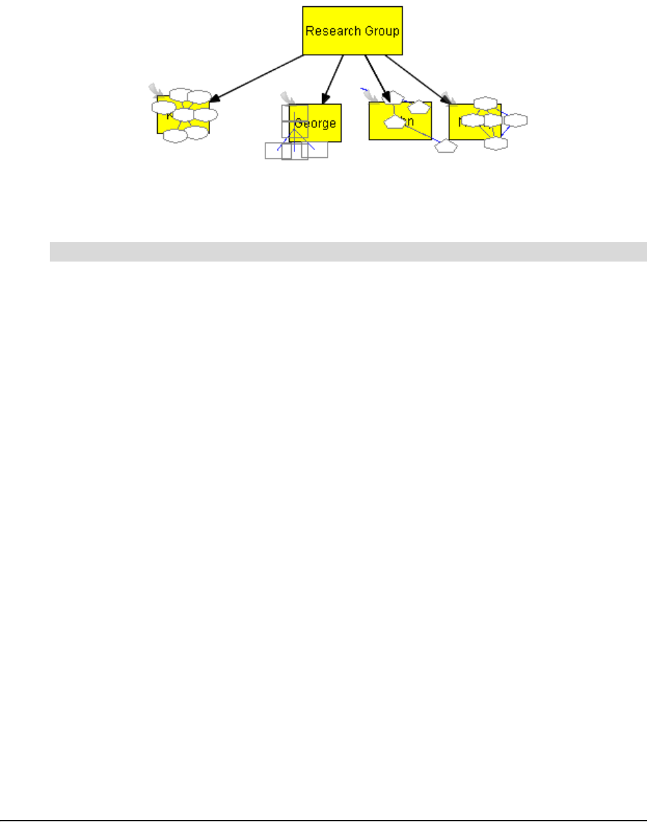
Getting to Know the Workspace 57
Viewing Sub-Levels
If you like, you can view small, ghost-like images of any diagrams that are associated with a
symbol’s sub-level. You can see at a glance which symbols have sub-level diagrams, as well as
the relative complexity of those diagrams.
The Sub-levels menu option also allows you to drag a selected symbol into any symbol’s sub-
level. For more information on dragging symbols directly into sub-levels, turn to page 73.
Select View > Sub-levels.
A small, faint image of the sub-level diagram appears inside each originating symbol.
Workspace Views
SMART Ideas software provides three distinct views of your work—Diagram, Outline and Global
view. You can switch between these views using the tabs at the top of the workspace.
Diagram and Outline View
The Diagram view is the view you’ll use most of the time. It’s the default view that gives you the
workspace and tools you need for making your diagrams.
To view a text-based, linear counterpart to your diagram, use the Outline view. This view is a
ready-made outline that your students can use for organizing a writing project. They can
brainstorm and develop connections between ideas in the Diagram view, and then toggle to the
Outline view when they’re ready to move from rough ideas to a finished document.
However, the Outline view isn’t only for viewing a text version of your diagram. You can also
develop a complete outline from scratch in this view. All the tools for creating new symbols and
labeled connectors, adding notes, hyperlinks and sub-levels, rearranging, revising and
reformatting your ideas are all available in this view. Any changes you make are immediately
reflected in the Diagram view.
To view sub-levels
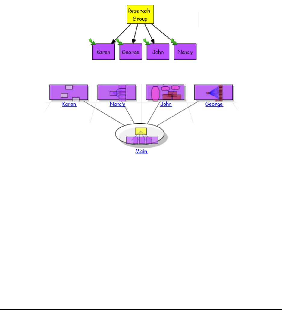
58 Getting to Know the Workspace
Global View
If you frequently use sub-level workspaces to create a complex, interconnected web of diagrams,
the Global view provides a useful overview of all your work. This view is a three-dimensional
depiction in miniature of every diagram at every level, so you can conveniently see everything at
once and instantly access any diagram with a mouse click. In addition, the link between the sub-
level diagram and its associated upper-level symbol is clearly shown, so it provides a useful road
map to your multi-dimensional workspace.
For example, if you created a diagram on the main level, in which each symbol represented a
student in a science research group, you might capture the outline of each student’s project in a
sub-level diagram that’s associated with their name.
In the Global view, the symbols and their sub-levels appear as follows:
The Global view displays a miniature image of the actual diagram that occupies each sub-level.
Click on any of the links to access the Diagram view of that workspace.
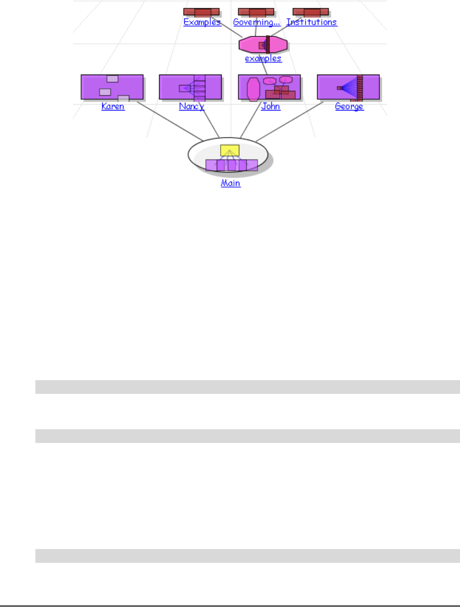
Getting to Know the Workspace 59
Any changes that you make in the Diagram view are immediately reflected in the Global view. For
example, if you add two sub-levels below the John workspace, the Global view changes
accordingly:
Maximizing the Workspace
When making a concept map presentation to a group, use Present (full screen) mode to close the
toolbars and maximize the viewing area. You can still access all toolbar functions via menu
options.
You can selectively enlarge the SMART Ideas workspace by hiding:
• the Standard toolbar
• the Formatting toolbar
• the Gallery toolbar
You can also click and drag the Gallery sidebar to make it wider or narrower.
Click the Present button on the Formatting toolbar.
Clear the selection of View > Toolbars > Standard to hide the Standard toolbar.
Clear the selection of View > Toolbars > Formatting to hide the Formatting toolbar.
Clear the selection of View > Toolbars > Gallery to hide the Gallery toolbar.
The workspace enlarges accordingly.
Click and drag the horizontal resize pointer on the Gallery sidebar.
To use Present mode
To hide the Standard, Formatting or Gallery toolbar
To change the width of the Gallery toolbar
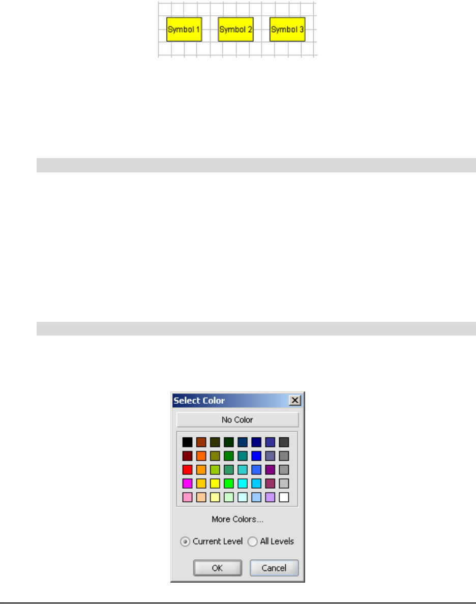
60 Getting to Know the Workspace
Using the Workspace Grid
Use the grid to precisely align the objects in your diagrams. When you activate the grid, a series of
faint, intersecting vertical and horizontal lines appears. Use this unobtrusive grid to assist in
aligning symbols.
You may have noticed that the three preceding symbols are perfectly aligned. When the grid is on,
the built-in “snap-to” functionality makes it easy to arrange objects: SMART Ideas software
automatically nudges the center of every object you move to the center of a grid box.
When the grid is off, the “snap-to” functionality is deactivated, and you again have free-moving
control over object placement.
Select View > Grid.
Changing the Background Color
The default background color for the Diagram view is plain white, with or without a grid. If you
prefer, you can change the background color of your current workspace or every workspace in
your SMART Ideas file. This feature does not affect the color of foreground elements of your
diagram, such as symbols, clip art, imported images and connectors.
NOTE: The background color appears when you print the diagram on a color printer.
1. Select Format > Background Color.
The Select Color dialog box appears.
To activate the grid
To change the background color
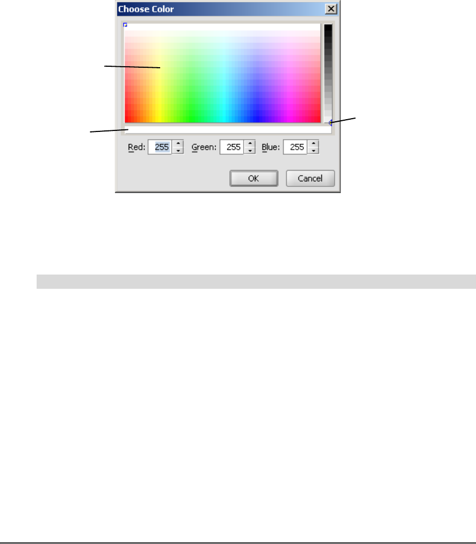
Getting to Know the Workspace 61
2. Select Current Level to change the background color of only the current workspace.
OR
Select All Levels to change the background color of all workspaces on all levels.
3. Click on a color in the 40-color palette.
OR
To create a custom color, click More Colors.
The Choose Color dialog box appears.
4. Click anywhere on the color swatch to change the hue and saturation, and then move the
slider in the color gradient to change the luminescence (brightness). Alternatively, you can
change the Red, Green and Blue values by selecting or entering number values.
5. Click OK.
Select Format > Background Color.
The Select Color dialog box appears.
Click the No Color button.
The background color disappears from the current and from all sub-level workspaces as well.
Applying a Color Scheme to Your Diagram
Give your diagrams a professional, uniform appearance by applying a color scheme to the
background, symbols, symbol borders and connectors. You can use one of the color schemes
provided with SMART Ideas software, create (and save) your own color schemes or edit existing
schemes.
To remove the background color
Move the slider to
adjust brightness
Click anywhere
to change hue
and saturation
Preview area
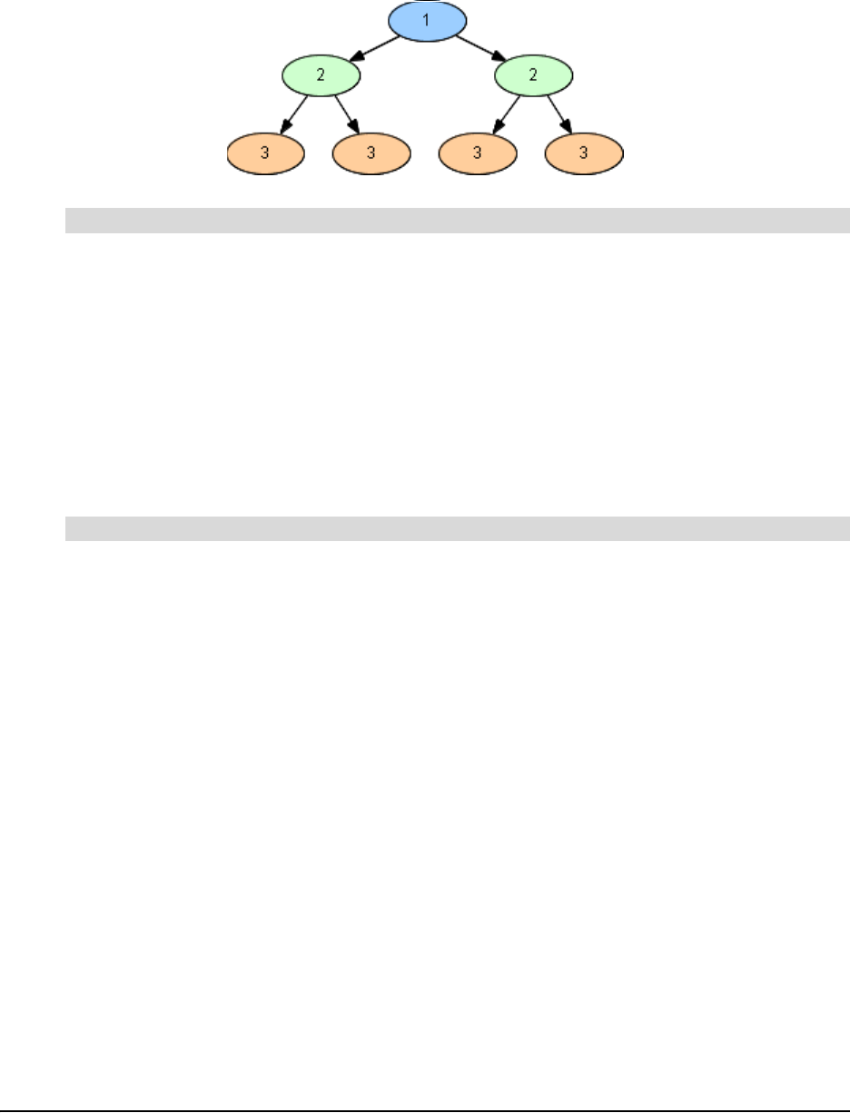
62 Getting to Know the Workspace
Apply a color scheme to an existing diagram and the symbols receives a color based on their
position within the diagram's hierarchy. Each first-level symbol has the same color, each second-
level symbol has the same color, and so on.
1. Select Format > Color Scheme.
The Create/Edit Color Scheme dialog box opens.
2. Select the Standard tab if it's not already selected.
3. Select the color scheme you'd like to apply to your diagram, and then press Apply.
OR
Double-click the color scheme you'd like to apply to your diagram.
SMART Ideas software applies the color scheme to the diagram's background, text, symbols,
symbol outlines and connectors.
1. Select Format > Color Scheme.
The Create/Edit Color Scheme dialog box opens.
2. Select the Custom tab if it's not already selected.
3. Click the color swatch to the left of Background.
A color palette appears.
4. Select a color for the diagram's background.
NOTE: Click More Colors to select a color that doesn't appear in the palette.
5. Repeat this process for the remaining items on the Custom tab.
6. After you've selected all the colors, type a name for the color scheme in the Name box, and
then press Save Scheme.
The custom color scheme is now available from the Standard tab.
7. If you want to apply the color scheme to the diagram, press the Apply button.
8. Click the Cancel or Close button to close the dialog box.
To apply a color scheme to a diagram
To create and save a custom color scheme
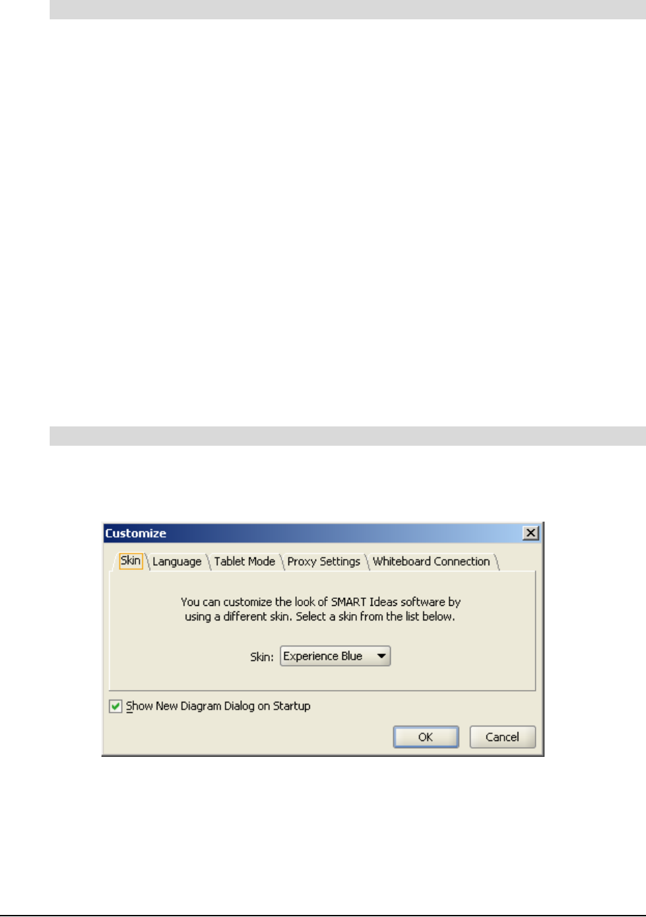
Getting to Know the Workspace 63
1. Select Format > Color Scheme.
The Create/Edit Color Scheme dialog box opens.
2. Select the Custom tab if it's not already selected.
3. Click the Load Scheme arrow, and then select the color scheme you'd like to edit.
4. Click the color swatch to the left of Background.
A color palette appears.
5. Select a color for the diagram's background.
NOTE: Press More Colors to select a color that doesn't appear in the palette.
6. Repeat this process for the remaining items on the Custom tab.
7. Enter a name for this scheme in the Name box, and then click Save Scheme.
The modified custom color scheme is now available from the Standard tab.
8. If you want to apply the color scheme to the diagram, click the Apply button.
Changing Skins
You can change the look of SMART Ideas software by changing its skin. Fourteen skins are
available that alter the color of the scroll bars and menu options when they’re highlighted.
1. Select Tools > Customize.
The Customize dialog box appears.
2. Click the Skin tab.
3. Click the Skin scroll-down arrow, and then select another color scheme from the list.
4. Click OK.
A Restarting SMART Ideas message appears.
5. Click Yes.
To edit an existing color scheme
To change the SMART Ideas software skin
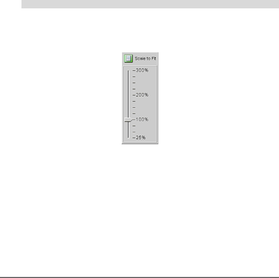
64 Getting to Know the Workspace
6. If you have unsaved changes in you SMART Ideas file, the Save Modifications dialog box
appears. To save your work and restart SMART Ideas software, click Save. To restart SMART
Ideas software without saving your work, click Don’t Save.
SMART Ideas software exits and then opens automatically in its new skin.
Using the Zoom Feature
Use the Zoom feature to magnify or reduce the size of the workspace, zooming in or out so you
can see a more detailed or general view of your diagrams. SMART Ideas software has a zoom
slider on the toolbar that provides continuous zoom options between 25% and 300%. A non-
continuous zoom feature is available in increments that range from 25% to 100% from the View >
Zoom menu.
The Scale to Fit setting adjusts your view automatically so you can see all the objects in the
workspace (at optimal zoom) without scrolling.
1. Click the Zoom button on the Standard toolbar.
A Zoom slider appears.
2. Drag the slider to the zoom level that you want.
OR
Click the Scale to Fit button to view all the objects in the workspace at an optimal zoom level.
Moving Around the Workspace
If you click the Pan button, you can drag the workspace in any direction, changing your view easily
and accurately without resorting to the scroll bars.
While the Pan button is depressed, you can still click on individual objects to select them. If you
click the CTRL or SHIFT key, you can select multiple objects in this way too. Once objects are
selected, click and hold again on the object (or one of several), and then drag the cursor to move
them.
To change the magnification of a workspace
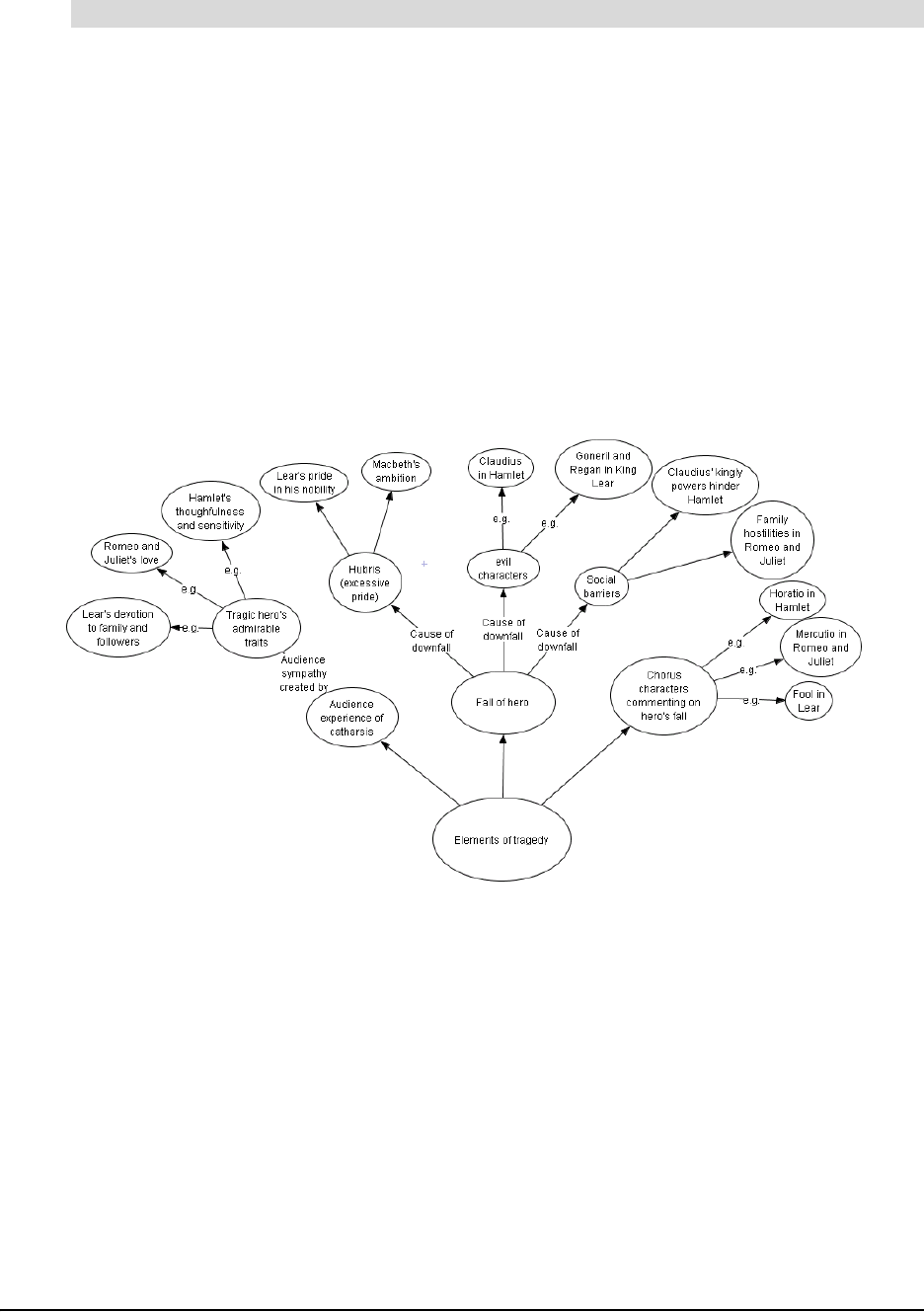
Getting to Know the Workspace 65
1. Click the Pan button on the Standard toolbar.
2. Click, hold and drag in any direction on the workspace.
3. Click the Pan button to deactivate it and restore normal click-and-drag selection behavior.
Shrinking and Expanding Diagram Trees
Concept maps are almost always hierarchical, beginning with broad, general concepts and then
branching out into more specific details. This hierarchical organization gives your diagrams a tree-
like appearance. Think of the main idea or topic symbol as the trunk of a tree that branches into
related subsidiary ideas, which can sprout many smaller branches of supporting details.
Note the tree-like structure of the diagram below. This diagram explores the characteristics of
literary tragedy, starting with the generic elements common to all tragedies and ending with
specific Shakespearean tragedies that illustrate those elements.
An elaborate diagram, such as the one on the previous page, is both visually intimidating and
difficult to grasp when viewed in its entirety. For the sake of clarity, you may want to hide the
symbols that reside on the branch ends until you’re ready to discuss them. This way, your students
can focus on general concepts first, and then you can selectively reveal supporting details—but
only when you’re ready to discuss them.
SMART Ideas software lets you expand or collapse either all trees on the current level or selected
branches of a diagram tree, one level at a time.
NOTES:
• If you save the file with collapsed or expanded trees, the file re-opens in the identical state.
• You can also expand and collapse trees in the Outline view. Click on a topic’s number and the
Expand or Collapse icon appears.
To move the workspace with the Pan feature
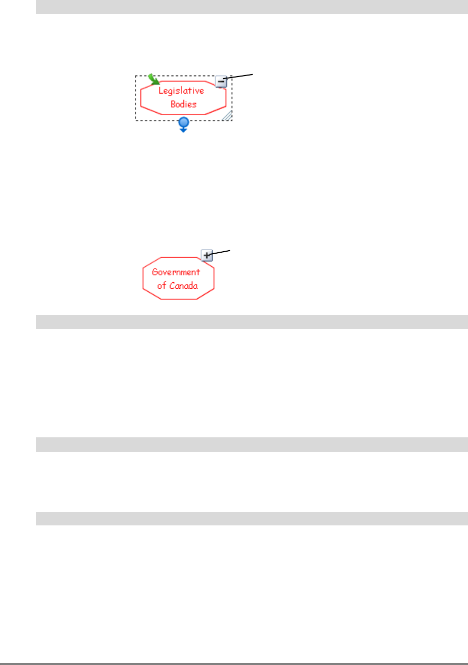
66 Getting to Know the Workspace
1. Select the symbol from which you want to hide all subsidiary sub-topics.
2. Click the Hide Sub-topics icon.
All the branches that emerged from the selected symbol disappear from view, so only the
selected symbol is displayed.
OR
Select View > Sub-topics > Hide.
You’ll notice the appearance of a new icon in the symbol’s selection rectangle. This is the
Show Sub-topics icon. Click this icon to expand the tree by a single level.
1. Select the symbol from which you want to expand the tree.
2. Click the Show Sub-topics icon.
OR
Select View > Sub-topics > Show.
All the branches you previously created beyond this symbol appears.
Select View > Sub-topics > Hide All.
All diagrams collapse down to their single, originating symbols.
Select View > Sub-topics > Show All.
All diagrams expand fully, displaying all branches at once.
To hide one level of a tree
To show one level of a tree
To hide all trees on the current level
To show all trees on the current level
Hide Sub-topics icon
Show Sub-topics icon
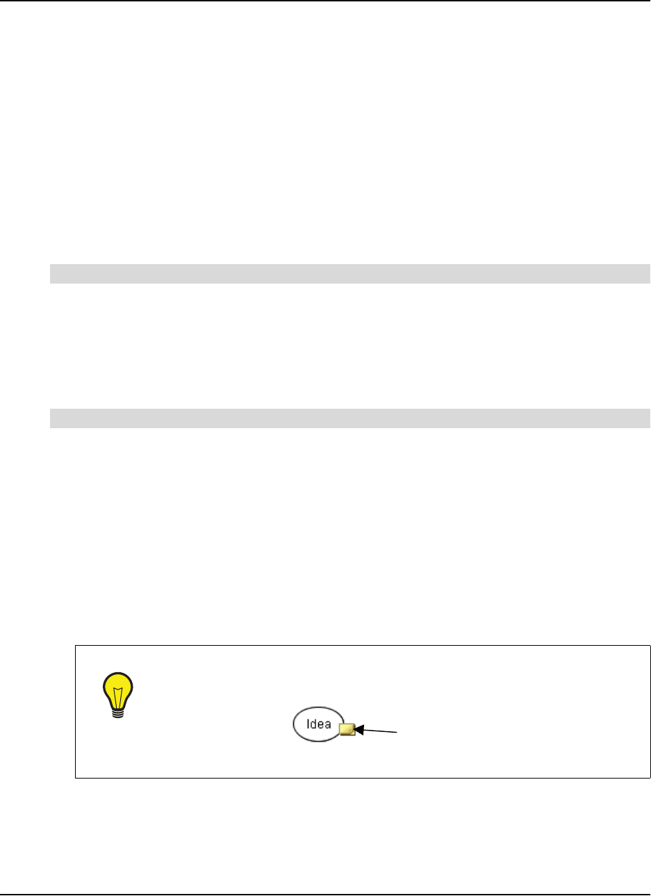
Working with Text 67
Working with Text
Symbols and connectors can be labeled with titles or descriptive text to make your diagram more
meaningful to others.
SMART Ideas software enables you to:
• perform full text editing and formatting (this page)
• check your spelling (page 68)
• find and replace text (page 69)
Editing Text
It’s easy to edit the text labels for symbols and connectors.
1. Type some text on the SMART Ideas workspace or in a selected symbol’s text box.
NOTE: Do not press the ENTER key on the keyboard.
2. Press the ALT+ENTER keys on the keyboard twice.
A blank line appears.
1. Select a symbol or connector.
2. Click the selected object again, and then edit the text in the text box that appears.
OR
Right-click on the selected object, select Edit Label, and then edit the text in the text box that
appears.
3. Press the ENTER key on your keyboard.
OR
Click once outside the text box.
To insert a blank line
To edit object labels
TIP
For lengthy text entries, attach a note to the symbol. When you move your
mouse pointer over the Note icon, the note appears in an editable text box.
Turn to page 41 for more information on attaching notes to symbols.
Note Icon

68 Working with Text
Formatting Text
The easiest way to change the font, size and weight of text is with the buttons on the Formatting
toolbar.
1. Select the symbol(s) or connector(s) that you want to modify.
2. To change the font type, click the Font button, and then select an alternative from the list.
3. To change the font size, click the Font Size button, and then select a point size from 8 to 72.
4. To change the font to bold or italic, click the Bold or Italic button.
NOTE: Because some fonts do not support bold and italic properties, these buttons are not
always available.
5. To change the font color, click the Font Color button, and then select a color from the palette
(or click the More Colors button to customize the color).
Checking Your Spelling
When you create a diagram, use the Spell Check feature to check your symbol and connector text.
This feature alerts you to any words that are repeated or misspelled and offers suggestions for
change. You can check the spelling of your text in the current level or in all sub-levels as well.
1. Select Tools > Spell Check > Current Level or Tools > Spell Check > All Levels.
When a misspelled or repeated word is encountered, the Check Spelling dialog box appears.
A misspelled or repeated word appears in the Not in dictionary box and a suggestion for
change appears in the Change to box.
If no errors are found, a message appears telling you that the spell check is complete.
2. Accept or reject the results of the spell check as follows:
a. To accept the suggested word, click the Change button.
OR
Select a word from the Suggestions list, and then click the Change or Change All
buttons.
OR
Type a correction of your own in the Change to field, and then click the Change or
Change All buttons.
b. To retain the original word (ignoring the spell check feature’s advice), click the Ignore
button, or click the Ignore All button to retain every occurrence of the original spelling.
c. To add the word to the Spell Check dictionary, click the Add button.
When the Spell Check is complete, the Check Spelling dialog box disappears.
To change the font type, size and weight of a label
To check your spelling

Working with Text 69
1. Click the scroll-down arrow under Dictionary language.
2. Select another dictionary from the list.
Finding and Replacing Text
When you need to review or change text in either the Diagram view or the Outline view, you can
search for and replace text in the current workspace or include all sub-levels.
1. Select Edit > Find Text.
The Find dialog box appears at the bottom of the workspace.
2. Enter the text that you want to find in the Text to find box.
You can type up to 255 characters in this box. The text scrolls horizontally as you type.
3. To find only separate words (not characters embedded in other words), select Whole words
only. For example, select this option to find “run” but not “running.”
4. To find only words that have a specific pattern of uppercase and lowercase characters, select
Match case.
5. To restrict your search to the current level only, select Current level. To expand your search to
include all sub-levels as well, select All levels.
6. Click the Search button.
SMART Ideas software selects the first occurrence of the text in either a symbol or connector
label. The text is displayed as it appears in relation to other levels in bold text in the display
area.
If the word or phrase isn't found, a No Search Result message appears in the display area.
7. Click the Next button to find subsequent occurrences of the text.
8. Click the Hide button in the upper-right corner of the Find dialog box.
1. Select Edit > Replace Text.
The Find dialog box appears at the bottom of the workspace.
2. Enter the text that you want to replace in the Text to find box.
You can type up to 255 characters in this box. The text scrolls horizontally as you type.
3. Enter the replacement text in the Replace with box.
To replace only separate words (not characters embedded in other words), select Whole
words only. For example, select this option to replace “run” but not “running.”
To replace only words that have a specific pattern of uppercase and lowercase characters,
select Match case.
4. To restrict your search to the current level only, select Current level. To expand your search to
include all sub-levels as well, select All levels.
To change the Spell Check dictionary
To find text
To replace text
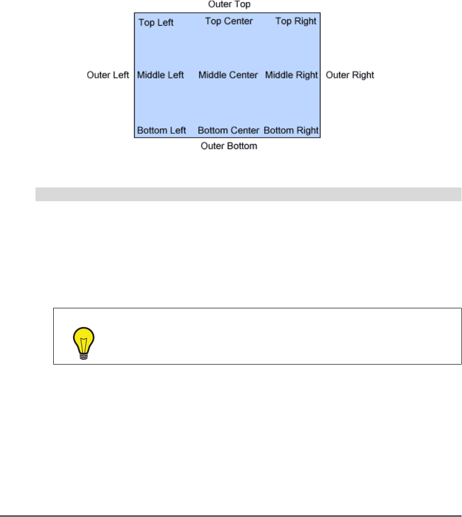
70 Working with Text
5. Click the Search button.
6. Click the Replace Selected button to replace the current selection with replacement text.
OR
Click the Replace All button to replace every occurrence of the text.
Changing Text Placement
You can place text anywhere you'd like within a symbol (or outside of a symbol) with the Text
Placement menu option.
1. Select the symbol or symbols that contain text.
2. Select Symbol > Text Placement.
OR
Press the Text Placement button drop-down arrow.
3. Select one of the 13 options for text placement.
NOTES:
• If you select more than one symbol, the same text placement is applied to each.
•The Text Placement button changes appearance to show the text placement for the currently
selected symbol.
• If you select a text placement option while no symbol is selected, that placement applies to the
next symbol you create.
To change the placement of a symbol's text
TIPS
• Use the Outer Top placement to create a title for a symbol.
• Use the Outer Bottom placement to create a caption.
Text Placement Options
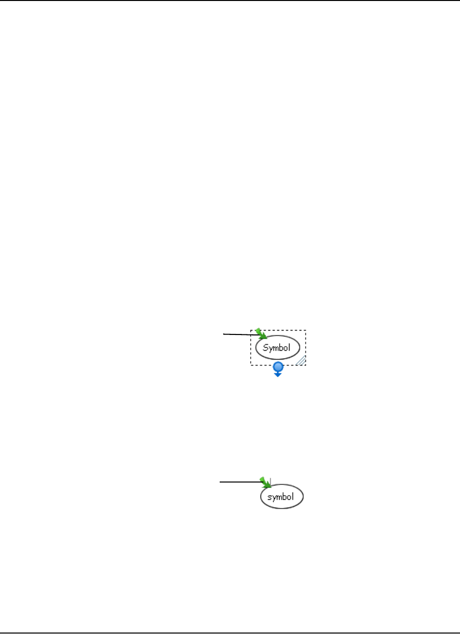
Adding Layers and Links to Diagrams 71
Adding Layers and Links to Diagrams
You can add depth to your diagrams by adding levels; you can also extend the reach of your
diagram by adding links to local files and Web sites.
In this section, you’ll learn how to:
• create layered diagrams (this page)
• show sub-levels (page 73)
• navigate within layered diagrams (page 74)
• link any file, program, e-mail address or website to a symbol (page 74)
• remove and replace links (page 77)
Creating Layered Diagrams
Every symbol in a diagram is a potential gateway to another diagram that you can create on a sub-
level of that symbol. You can use sub-levels to illustrate or expand on information. You can also
use them to hide information, so you can reveal details or examples when you want to, or when
your class is sufficiently prepared to understand them.
It’s easy to create a new sub-level or open an existing sub-level: Select a symbol, and then click
the Open Sub-level icon (the arrow in the upper-left corner of the symbol).The sub-level then
opens as a new, blank workspace, in which you can create a diagram, write a few lines of
illustrative text, insert a picture, etc.
You can continue creating more sub-levels, or click the Back button (located on the left edge of the
Standard toolbar) to return to the previous level. You can create an unlimited number of sub-levels
to contain related symbols, diagrams, text or graphics.
Any symbol with sub-level content displays the Open Sub-level icon—even when you haven’t
selected the symbol. To open a sub-level, click this icon.
Click to create
or open a new
sub-level
Click to open a
previously created
sub-level
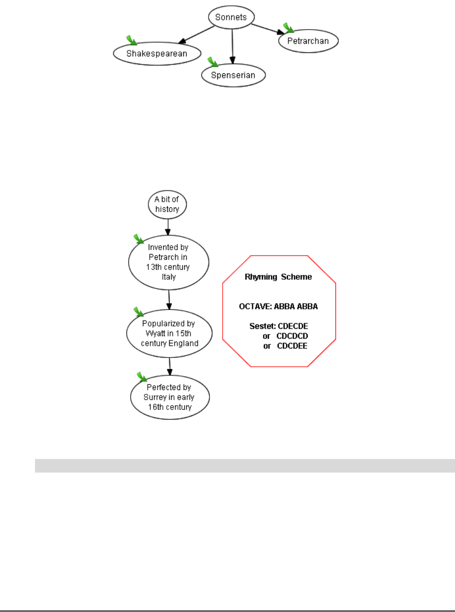
72 Adding Layers and Links to Diagrams
For example, for a lesson on the history of the sonnet, you could create a diagram that shows the
three major types of the sonnet form.
To keep your diagram simple and clear, relegate the illustrative information to each symbol’s sub-
level. Then, when your class is ready for more detailed information, click the Open Sub-level icon
to view it.
For example, if you click the Open Sub-level icon on the “Petrarchan” symbol, the following
diagram appears:
The “Petrarchan” Symbol Sub-Level
1. Select the symbol.
2. Click the Open Sub-level icon (the green, curved arrow in the top-left corner of the selection
rectangle).
A new, blank workspace opens.
To create a symbol sub-level
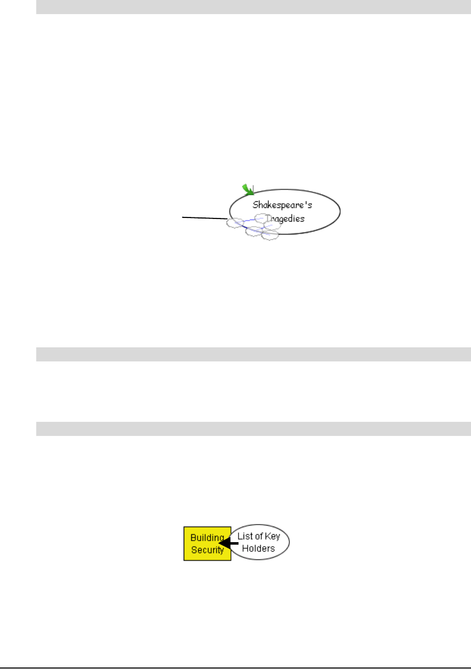
Adding Layers and Links to Diagrams 73
Click the Back button on the Standard toolbar.
OR
Click the watermark in the upper-left corner of the workspace (if it’s displayed).
Showing Sub-Levels
To view the diagrams on underlying sub-levels at a glance, activate the Sub-levels menu option.
This menu option displays a miniature, ghostly image of the sub-level diagram inside the
originating symbol.
When Sub-levels is active, symbols also become functionally transparent. To move a symbol to
the sub-level of another symbol, drag the symbol (or multiple connected symbols) onto the target
symbol and watch the dragged symbol(s) recede and then disappear into the destination symbol’s
sub-level. Open the sub-level (by clicking the green Open Sub-level arrow icon) to view the
symbol you dropped into it.
Select View > Sub-levels.
A small, faint image of the sub-level diagram appears inside each originating symbol.
1. Select View > Sub-levels, and then select a symbol.
NOTE: You can’t drop a selected symbol onto a sub-level if the symbol you’re dropping is
connected to another symbol.
2. Move the symbol or a selected group of symbols over top of another symbol.
When the moving symbol reaches the middle of the receiving symbol, it gradually disappears
from view as it sinks into the receiving symbol's sub-level. A small, ghost-like version of the
moved symbol appears inside the receiving symbol, and an Open Sub-level icon appears
next in the upper-left corner.
To return to the originating symbol (in the previous layer)
To view sub-levels
To drop a symbol or diagram into a sub-level
Miniature view
of diagram in
sub-level

74 Adding Layers and Links to Diagrams
3. Click the Open Sub-level icon to view the symbol you moved.
4. Click the Back button on the Standard toolbar to return to the original symbol level.
Navigating through Symbol Layers
Because any symbol can have a sub-level, and any sub-level can have further sub-levels, you
may lose track of where you are in a multi-layer diagram. There are a number of ways to stay
oriented:
• Click the Back button on the Standard toolbar to return to a higher level, or click a symbol’s
Open Sub-level icon to see the level below.
• Use the Navigator sidebar (see page 56 for details).
• Click the watermark level links. You’ll notice a watermark of faint blue text links on the top-left
corner of each level. Click on the different links in the watermark to return to the original (Main)
level or to the other sub-levels.
• Open the Global view (by clicking the Global tab) to view a map of all levels and sub-levels,
and instantly access them. For a detailed discussion of the Global view, see page 58.
•Select View > Go To > Go Home (CTRL+HOME) to return to the originating symbol level.
Creating Links to Websites, Files or Other Diagram Levels
Enrich your diagram with links to any website, a file or another level in the current diagram. A
hyperlink lets you quickly access any external sources of information to clarify, illustrate or expand
on an idea that a particular symbol represents.
Click here to view
the sub-level

Adding Layers and Links to Diagrams 75
Although you can add as many links to your diagram as you have symbols, you can create only
one link per symbol. After you add a hyperlink to a symbol, a Link icon appears in the lower-left
corner of that symbol. Click the icon to go directly to the associated website, file or diagram level
for that link.
1. Select a symbol.
2. Click the Add Link button on the Formatting toolbar.
The Insert Link dialog box appears.
3. Click Web page.
4. Enter the full Web address in the text box.
OR
Click the arrow, and then select a Web address from the list of links previously used. (This list
is empty if this is the first time you’ve created a hyperlink.)
TIP
The Internet is a great source of lesson materials, ideas for class projects and even
news from your local teachers’ association. Although you can always store favorite
websites in your Internet browser, it can be difficult to find the website you want
from a long list of favorites.
Use SMART Ideas software as a single source website management tool:
Associate favorite website links with connected, descriptive symbols in a single
SMART Ideas file, where they’re a mouse-click from view.
You can create a well-organized, connected diagram exclusively made up of
website links, and even add a link to a favorite file on your hard drive or network.
Either way, each time you click the Link icon, your Web browser (or Windows
Explorer) opens and the associated website (or file) appears.
To link a symbol to a website
Link Icon
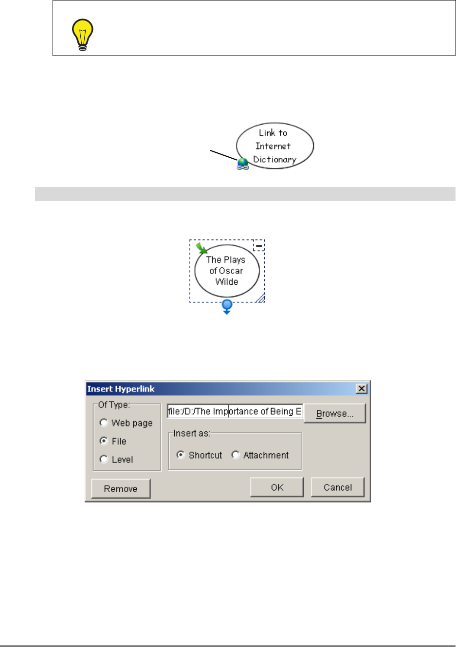
76 Adding Layers and Links to Diagrams
5. Click OK.
The symbol appears with a Link icon in its lower-left corner. To open the Web page that you
created a link to, click this icon.
1. Select a symbol.
2. Click the Add Link button on the Formatting toolbar.
The Insert Link dialog box appears.
3. Click File.
4. Click the Browse button.
The Open dialog box appears.
5. Navigate to the file that you want to link to.
6. Click the Open button.
The file path and name appear in the box.
TIP
Rather than manually typing a Web address into the Insert Hyperlink dialog
box, it’s easier—and often more accurate—to open your Web browser and
navigate to the website you want to link to. Then copy the address that’s in the
Address box of your browser and paste it into the Insert Hyperlink dialog box.
To link a symbol to a file
Click here to open
the link you created

Adding Layers and Links to Diagrams 77
NOTE: If the size of your file is a consideration, make sure Shortcut is selected. With
Shortcut selected, the file remains on your hard drive or network, and is opened from that
location. If you select Attachment, the file is actually attached to the SMART Ideas project file
and the file size enlarges accordingly.
7. Click OK.
The symbol appears with a Link icon in its lower-left corner. To open the file that you created a
link to, click this icon.
1. Select a symbol.
2. Click the Add Link button on the Formatting toolbar.
The Insert Link dialog box appears.
3. Click Level.
4. Click the arrow, and then select a level from the list of all levels in the current SMART Ideas
file.
5. Click OK.
The symbol appears with a Link icon in its lower-left corner. To open the linked level, click the
icon.
Removing and Replacing Links
Because you can add only one link to a symbol, you may need to alter a link so that it opens a
different file or Web page, or you may need to remove the link altogether.
1. Select the symbol with the link that you want to remove or replace.
2. Click the Link button on the Formatting toolbar.
The Insert Hyperlink dialog box appears.
3. To remove the link, click the Remove button.
OR
To replace the link, click a new link type (Web page, File, or Level), and then enter a new Web
address, or browse to a new file or diagram level.
4. Click OK.
To link a symbol to another level in the same diagram
To remove or replace a link
Click here to open
the link you created

78 Adding Layers and Links to Diagrams
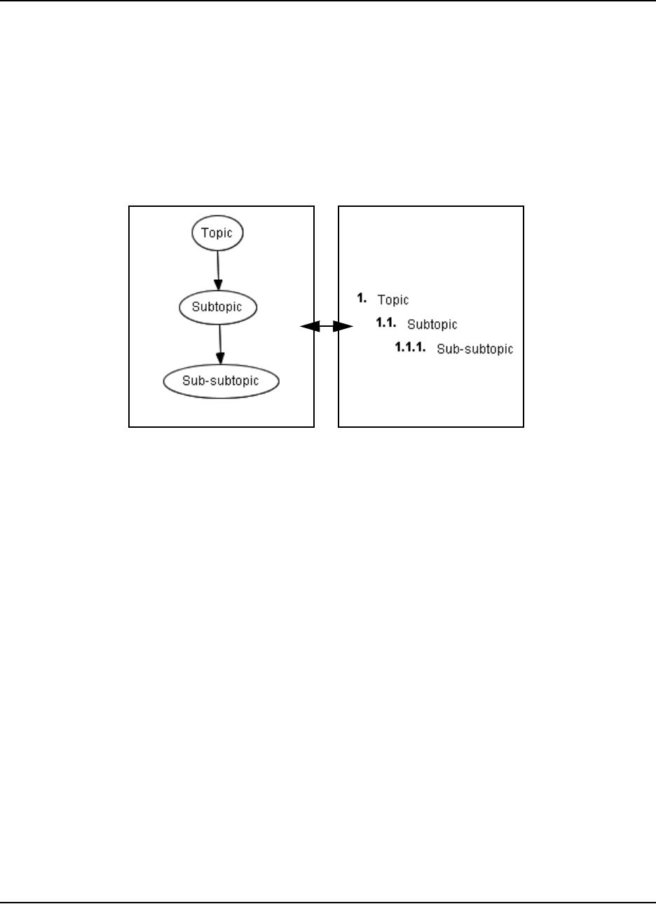
Working in Outline View 79
Working in Outline View
The graphically based Diagram view gives you all the tools you need for creating concept maps
that capture your ideas in a colorful and stimulating way. As you work in this view, SMART Ideas
software automatically generates a text-based, hierarchical view of the same information, called
the Outline view. This view displays only the text associated with symbols and labeled connectors,
and uses a numbering scheme and progressive indentation to convey diagram hierarchy.
In the figure below, note how the Diagram and Outline views show the same information in
different ways. Only the text and hierarchy appear in the Outline view; none of the graphical
aspects—such as symbol color and shape—are visible.
Switch back and forth between the Diagram and Outline view to demonstrate to students how an
outline is essentially the linear, textual counterpart of the tree hierarchies of a concept map.
You can also use Outline view on its own to develop an outline from scratch. Almost everything
you can do in Diagram view can also be done in Outline view, from creating symbols and sub-
levels to adding hyperlinks and notes, editing, formatting, reordering and printing. However, you
must use Diagram view for any graphically based activity, such as selecting symbol shape and
color, importing clip art and using icon-based connectors.
Understanding Outline View
Good writers often spend more time thinking and planning than writing. A major challenge for all
writers is effectively organizing their thoughts. A formal outline lets you move from a random list of
topics to a deliberate information map that lets you see more clearly how your ideas can be best
arranged to promote clarity and understanding in the reader.
In the Outline view, diagram hierarchy is conveyed by a numbering scheme together with
progressive levels of indentation. The tools in the Outline view help you write, rearrange and
organize your ideas for a complex writing project in outline form. The result is a conventional
outline of the kind typically created prior to writing any complex document. Unlike a conventional
outline, however, the Outline view also lets you add notes and hyperlinks to topics and even create
new sub-levels.
Diagram View
Outline View
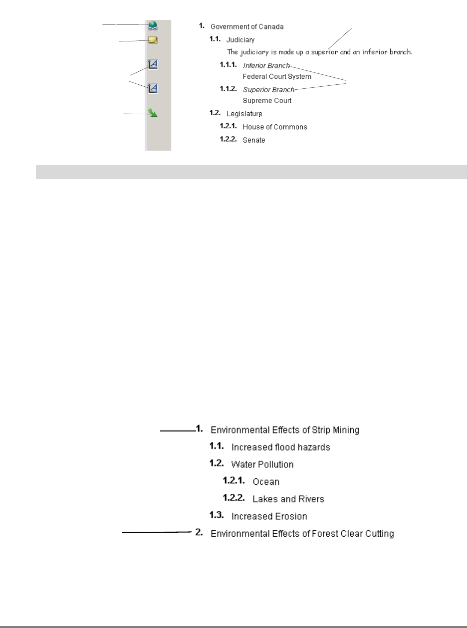
80 Working in Outline View
You can click on icons in the Icon Sidebar to view the notes, connector text, links and sub-levels
associated with corresponding topics.
Click the Outline tab at the top of the workspace.
OR
Select View > Outline View.
A text-based view of the diagram appears.
Creating Topics
When you create a new topic in the Outline view, it always appears immediately below—and on
the same level as—the currently selected topic. So, if you want to create a sub-topic below an
existing topic, you must either place the cursor on an existing sub-topic, or demote the new topic to
a sub-topic after you’ve created it.
In the example below, the topic 1. Environmental Effects of Strip Mining was the currently selected
topic. The new topic (Environmental Effects of Forest Clear Cutting) becomes topic #2 on the
same level, bypassing the five sub-topics under topic #1.
The topics you create in Outline view are automatically converted to symbols (in the last symbol
style that was selected) in Diagram view. They appear linked in a “tree” pattern that is dictated by
the outline hierarchy.
To switch to Outline view
View/Hide
Connector Text
Displayed
Connector Text
Go to Sub-level
Open Link
Displayed Note
View/Hide Note
Icon Sidebar Diagram Workspace
Originally Selected Topic
New Topic
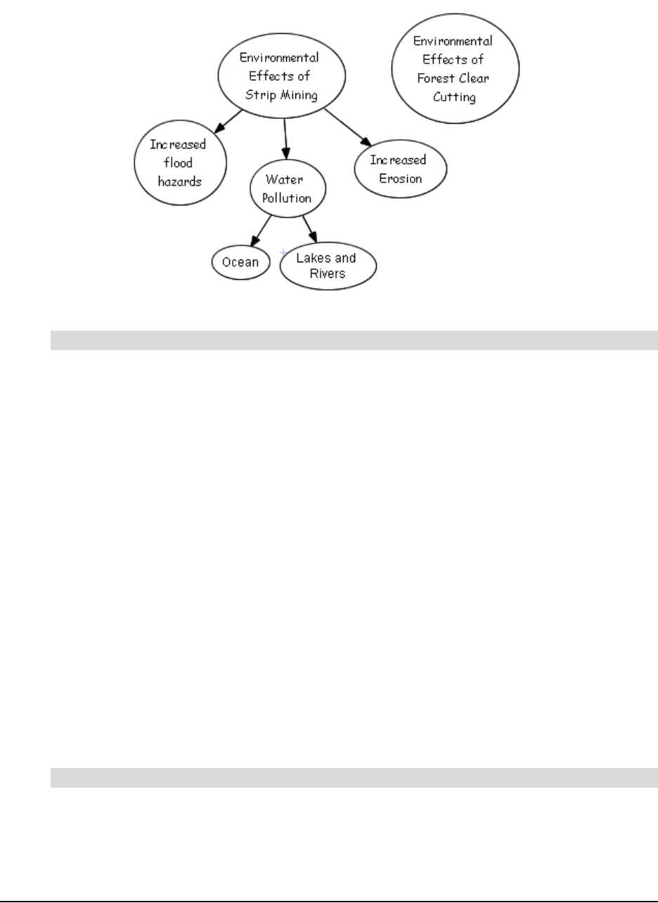
Working in Outline View 81
For the example above, the resulting “tree” in Diagram view would appear as follows:
1. Click the New Topic/Symbol button on the Standard toolbar.
OR
Select a topic on the same level as the new topic, on the line directly above where you want
the new topic to appear.
OR
Select Main at the top of the workspace if you want the topic to appear at the top of the outline.
2. Press the ENTER key on your keyboard.
A numbered text entry box appears.
3. Type the topic text.
4. Press the ENTER key.
A new topic appears on the same level as the originally selected topic.
Creating Notes, Links and Sub-levels
You can do almost everything in Outline view that you can do in Diagram view, and that includes
creating topic sub-levels, links and adding notes to topics.
NOTE: Although you can’t create connectors in Outline view, you can view and edit connector text.
1. Select the topic.
2. Click the Add Note button on the Formatting toolbar.
The selected topic expands to include an empty line underneath the topic text.
To create a new topic
To add a note to a topic
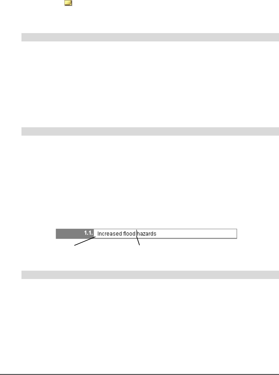
82 Working in Outline View
3. Type your note in the empty line.
4. Click outside of the text box to commit the text.
A Note icon appears in the Icon Sidebar. Click the icon to view the note.
NOTE: To view the note without clicking the Note icon, select View > Notes > Show or Show
All.
1. Select the topic.
2. Click the Add Link button on the Formatting toolbar.
The Insert Link dialog box appears.
3. Click website, file or level in Of Type.
4. Specify or browse to the destination.
5. Click OK.
A Link icon appears in the Icon Sidebar. Click the icon to go directly to the link source.
1. Select the topic.
2. Select View > Go to > Inside.
A new workspace opens on the newly created sub-level.
3. Press the Back button on the Standard toolbar to return to the originating topic.
Editing Text in Outline View
When you select a topic, a text-edit box appears, allowing you to freely change and add text to the
original topic. Reposition the flashing text entry cursor as needed.
Editing and adding text to connector labels and notes is as easy.
1. Click the View Connector Text icon in the icon sidebar.
OR
Select Outline > Connector Text > Show or Show All.
The connector text appears in italics in a new line above its associated topic.
2. Select the connector text, and then edit it as required.
To add a link to a website, file or level
To add a sub-level to a topic
To edit connector label text
Selected topic
Flashing cursor

Working in Outline View 83
1. Click the View Note icon in the icon sidebar.
OR
Select View > Notes > Show or Show All.
The note text appears on a new line below its associated topic.
2. Select the note text, and then edit it as required.
Reorganizing Your Outline
You can change the organization of a diagram to reflect changed or developing trains of thought as
easily in Outline view as you can in Diagram view.
You can click and drag a topic to move it up or down within the outline in its current level only.
However, if you want to move a topic outside of its current level, either promoting or demoting it
within the outline hierarchy, use the Promote and Demote buttons on the Standard toolbar.
Click and drag the topic above or below its current location within its current level only.
OR
Click the Promote button to move the topic up one level.
OR
Click the Demote button to move the topic down one level.
1. Select a symbol.
2. Click the Delete button on the Standard toolbar.
OR
Select Edit > Delete.
OR
Press the DELETE key on your keyboard.
Hiding and Revealing Topics in Outline View
Like in Diagram view, you can work with all or selected topics displayed or keep sub-topics hidden
from view.
For the sake of clarity, you may want to hide sub-topics. This way, your students can focus on
general concepts first, and then you can selectively reveal supporting details—but only when
you’re ready to discuss them.
NOTE: If you save the file with hidden or shown sub-topics, the file re-opens in the identical state.
To edit a note
To alter the hierarchy of a diagram
To delete a topic (and its associated connector)
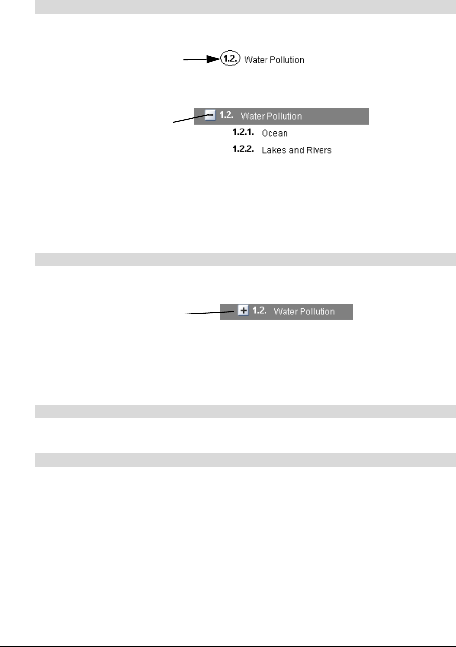
84 Working in Outline View
1. Select the number associated with the topic from which you want to hide the tree.
The Hide Sub-topics icon appears.
2. Click the Hide Sub-topics icon.
OR
Select View > Sub-topics > Hide.
All sub-topics below the selected topic disappear. You’ll notice the appearance of a Show
Sub-topics icon. Click this icon to view the sub-topics that were hidden.
Click the Show Sub-topics icon beside the topic you want to expand.
OR
Select View > Sub-topics > Show.
All the sub-topics associated with all topics appear.
Select View > Sub-topics > Hide All.
Select View > Sub-topics > Show All.
To hide one level of a tree
To reveal one level of a tree
To hide all sub-topics
To show all sub-topics
Click Here
Hide Sub-topics Icon
Show Sub-topics Icon

File Management 85
File Management
Managing SMART Ideas software project files (.ipr files) is very much like managing files in any
other Windows application. For example, you can create a new file, save it for later viewing and
revision, or print it. And, like many familiar word processing applications, SMART Ideas software
comes with many file templates to help get you started, and you can also create your own custom
templates for those diagrams that you use often.
In addition to these standard file management tasks, you can export your files in many different
formats so that people without SMART Ideas software can still see your work.
For example, you can export your diagram as a WordPerfect, Word, AppleWorks or plain text file.
With Word and WordPerfect exports, you can choose to export both the Diagram and Outline view
of your SMART Ideas file. However, the AppleWorks and plain text files you create are based on
the text-only Outline view of your SMART Ideas file. You can also save your Diagram view as
.jpeg, .png or .svg images. So, if you like, you can accompany a plain-text version of the Outline
view with an image of the Diagram view in any of the three image formats.
You can also publish your SMART Ideas file onto the Web so that anyone with a Web browser can
access your work.
Creating a New SMART Ideas File
When you create a new SMART Ideas file, you can use a template or start from a blank
workspace.
1. Select File > New.
The New SMART Ideas Diagram dialog box appears with Blank Diagram selected on the
Documents tab.
2. To create a new template, select Blank Template.
OR
To base your new diagram on an existing or supplied template, click the Templates tab, and
then select one of the templates from the list.
3. Click the Open button.
An untitled, blank workspace appears.
To create a SMART Ideas file

86 File Management
Opening a SMART Ideas File
If you’re working in SMART Ideas software and want to open a recently used file, click the File
menu. You’ll see the last four SMART Ideas software project files that you worked on at the bottom
of the menu. Click any one of those files to instantly load it into the workspace.
1. Select File > Open.
The Open dialog box appears.
2. Select an .ipr file.
3. Click the Open button.
Saving a SMART Ideas File
You can save your file to your hard drive or a network location, as you would in any other program.
1. For a previously saved file, select File > Save to save the file in the same format and with the
same name, or click the Save button.
OR
Select File > Save As to save the file with a different name or in a different location.
2. If you’re saving the file for the first time, enter a file name in the Save As dialog box, and then
then click the Save button.
Exporting a SMART Ideas File to Word, WordPerfect, AppleWorks or a
Plain Text File
If you need to send your SMART Ideas file to someone who doesn’t have SMART Ideas software,
convert your file to a Microsoft Word, AppleWorks, WordPerfect or plain text file. When you do this,
you’re not making the information in your diagrams accessible to more people; you’re also
transforming the text-based Outline view into a fully editable file that can serve as the basis for a
longer writing project in any of those formats.
When you export to Word or WordPerfect, the two working views of SMART Ideas software—the
graphically based Diagram view and the text-based Outline view—are both exported. The
Diagram view appears as a single, uneditable graphic at the top of the page, while each text line in
the Outline view appears as a separate, fully editable bulleted point, indented according to the
original symbol’s place in the diagram hierarchy.
To open a SMART Ideas file
To save a SMART Ideas file
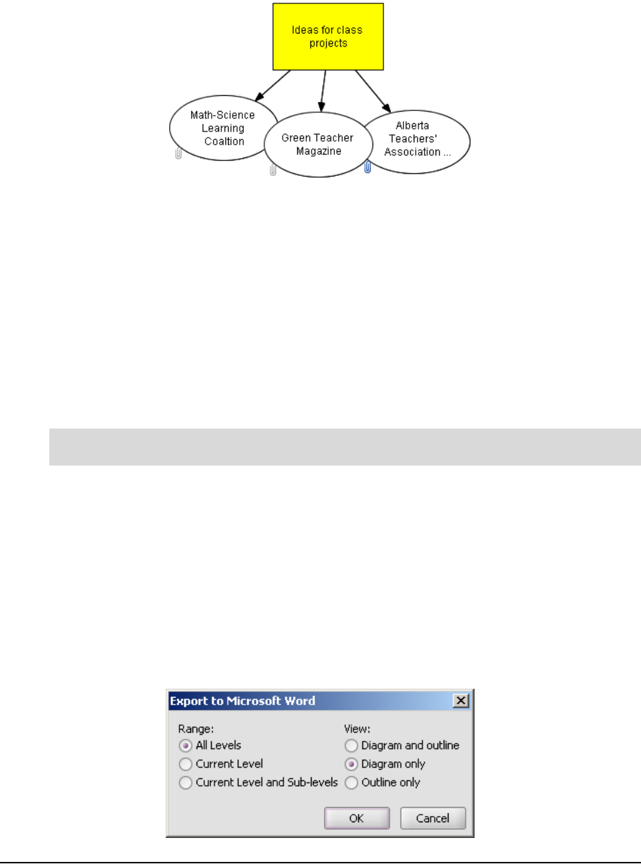
File Management 87
For example, a simple, two-level diagram would convert into a word processing document as
follows:
• Ideas for class projects
– Math-Science Learning Coalition
– Green Teacher Magazine
– Alberta Teachers' Association Science Council
You can edit each bulleted point, adding text to make them the lead sentence of several connected
paragraphs, or use them as separate headings for more extended discussions.
NOTE: If the diagram has sub-levels, those sub-levels are also converted on individual pages of
the resulting file. For example, if eight different sub-levels have been created from the original,
single Main page, the resulting file contains nine pages. Also, the symbols from which the sub-
levels originate appear as linked text that takes you to the sub-level when clicked.
1. Select File > Export > MIcrosoft Word.
OR
Select File > Export > WordPerfect.
OR
Select File > Export > AppleWorks.
OR
Select File > Export > Plain Text Document.
An Export to [Selected Application] dialog box appears.
To convert a SMART Ideas file to a Word, WordPerfect, AppleWorks or plain text
file

88 File Management
2. Select the level range you want to export under Range.
3. For Word and WordPerfect exports only, select the view (or views) you want to export under
View.
4. Click OK.
A Save dialog box appears.
5. Enter a file name in File Name, and then browse to an appropriate location for the resulting
file.
6. Click the Save button.
Exporting Workspace Views to the Web
It’s easy to create diagrams and then publish on the Internet or send them to people who don’t
have SMART Ideas software installed on their computers. You can save your diagrams in either a
graphical (Diagram view) or text-only form (Outline view) that’s ready for Web publication.
To save your diagrams in graphical form for the Internet, use the Export Diagram View to Web
menu option. This menu option saves your current diagram as a high-quality, Web-ready graphic
and retains all hyperlinks in the document after conversion.
To save your diagrams to the Internet in text-only form, use the Export Outline View to Web
(Text) menu option: This menu option converts the Outline view of your diagram into HTML format,
ready for online publication.
1. Select File > Export Diagram View to Web.
A Saving message appears as your diagram is converted.
2. Wait a few moments.
The converted diagram opens in your Web browser.
1. Select File > Export Outline to Web (Text).
NOTE: You can be in Diagram view when you select this menu option. An HTML file of the
Outline view is created.
2. Wait a few moments.
The converted text-only outline opens in your Web browser.
Printing a Diagram
You can print the current level of your diagram or the current level plus all associated sub-levels. If
a diagram is too large to fit on a single page, SMART Ideas software tiles the diagram onto as
many pages as necessary.
To export the Diagram view for Web publication
To export the Outline view for Web publication

File Management 89
If you'd like to shrink the diagram to fit on a single page or change the way the diagram is tiled, use
the Print Preview menu option. In Print Preview, you can also add headers and footers to your
printed pages, which can be centered or aligned on the left or right side of the page.
1. Select File > Print Current Level to print only the current level of your diagram
OR
Select File > Print All Levels to print every level of your diagram
The Print dialog box appears.
2. Specify the printer you want to use in the Name box.
3. Specify what you want printed in the Print range box.
4. Specify the number of copies you want printed in the Number of copies box.
5. Click OK.
Using Print Preview
In addition to using Print Preview to see how the diagram's levels look before you print them, this
menu option also lets you:
• change how large diagrams tile to several pages
NOTE: When a level is too large to fit on a single printed page, SMART Ideas software tiles
the diagram onto as many pages as necessary to accommodate the entire level. You can use
Print Preview to change the way the level is divided into separate pages.
• click and drag the page boundary (horizontal or vertical) to print only a specific area of the
page
• add a header or footer to a printed page
• print the current, selected or all levels
• shrink a large diagram to fit on a single page
1. Select File > Print Preview.
The Print Preview view of the file appears.
2. In the Level Sorter on the left, click the thumbnail for the level you want to tile.
The level appears in the preview area to the right. Dotted blue lines indicate where the page
breaks occur.
3. Adjust the page breaks by dragging the dotted lines anywhere you'd like.
NOTE: To restore the page breaks to their original positions, press the Reset button in the
lower-right corner.
To print a SMART Ideas file
To change how large diagrams tile to several pages

90 File Management
1. In the Level Sorter on the left, click the thumbnail for the level you want to tile.
The level appears in the preview area to the right.
2. Press the Fit to Page button in the lower right of the preview area.
The diagram shrinks to occupy only a single page when printed.
NOTE: To restore the page to its original size, press the Reset button in the lower right.
1. To print the level currently showing in the preview area, select Print current level from the
drop-down list.
OR
To print the selected levels, select Print selected levels from the drop-down list. (To select a
level to print, click the box in the upper-right corner of a level's thumbnail to make a check-
mark appear.)
OR
To print all the levels in a diagram, select Print all levels from the drop-down list.
OR
To print only part of the page, click and drag the page boundary (vertical or horizontal) to
specify a portion of the page.
2. Click the Print button.
Using Templates in SMART Ideas Software
A template is a document you can use as a pattern to create other documents of the same type.
The idea behind templates is that while you may create many documents, you generally create
only a few types of documents. Templates provide a place to store boilerplate symbols, notes and
connectors, reducing the amount of work necessary to set up new diagrams.
When you start SMART Ideas software, you’ll see a long list of templates from which to choose.
There are templates that have been specifically developed for social studies, science, language
arts and lesson planning.
You can also create your own templates for diagram formats that you use frequently. For example,
if you’re a language arts teacher, you might develop four individual templates devoted to each of
the major literary archetypes—tragedy, comedy, romance and irony— with symbols that capture
the generic elements of each archetypal plot. When you want to show how a particular literary
work fits within the framework of a literary archetype, you can adapt the template using specific
examples from that work.
To shrink a large diagram to fit on a single page
To print pages from within Print Preview
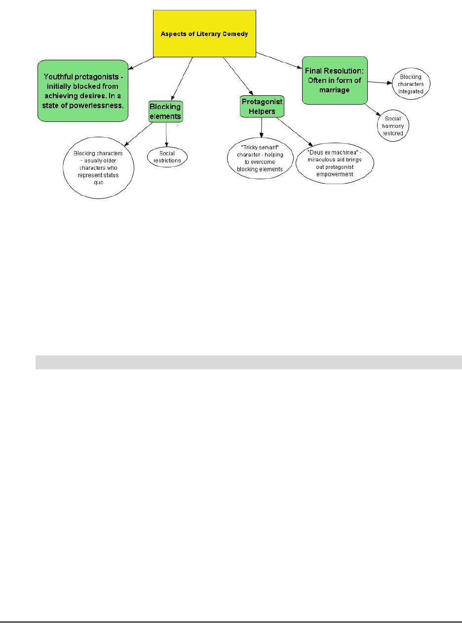
File Management 91
The following example is a template developed to show recurring elements in the genre of literary
comedy.
To create your own template, you can either:
• create a diagram as usual, select Save As, and then save it with the .ipt extension rather than
the default .ipr (Ideas project file) extension. Selecting the .ipt extension automatically
converts the SMART Ideas project file into a template.
• create a diagram, and then save it with the Save As Template menu option. This is described
in the procedure on the next page.
When you use the Save As Template option, your template is saved into My Documents\My
SMART Ideas Content\Templates. You can create as many folders as you like within
Templates.
1. Select File > Open Template.
2. The New SMART Ideas Diagram dialog box appears with <Blank Document> highlighted on
the Templates tab.
3. Select a template from the list.
4. Click the Open button.
The template opens.
5. Customize the diagram.
6. Click the Save button.
OR
Select File > Save or File > Save As.
The Save As dialog box opens.
7. Give your diagram a name, navigate to a folder, and then click the Save button. By default,
SMART Ideas software gives the file an .ipr (Ideas project) extension.
To use a provided template

92 File Management
1. Create a diagram.
OR
Open an existing diagram that you want to develop into a template.
2. Select File > Save As Template.
The Save as Template dialog box opens.
3. Type a name for the template.
4. Click the Save button.
The new template is stored in My Documents\My SMART Ideas Content\Templates.
OR
Save the template in a new sub-folder:
a. Click the Select button.
The Select a Category dialog box appears.
b. Click the New button, and then type a name in the new category box.
c. Click OK.
The new template is stored in My Documents\ My SMART Ideas Content\
Templates\[New Folder].
To create your own template
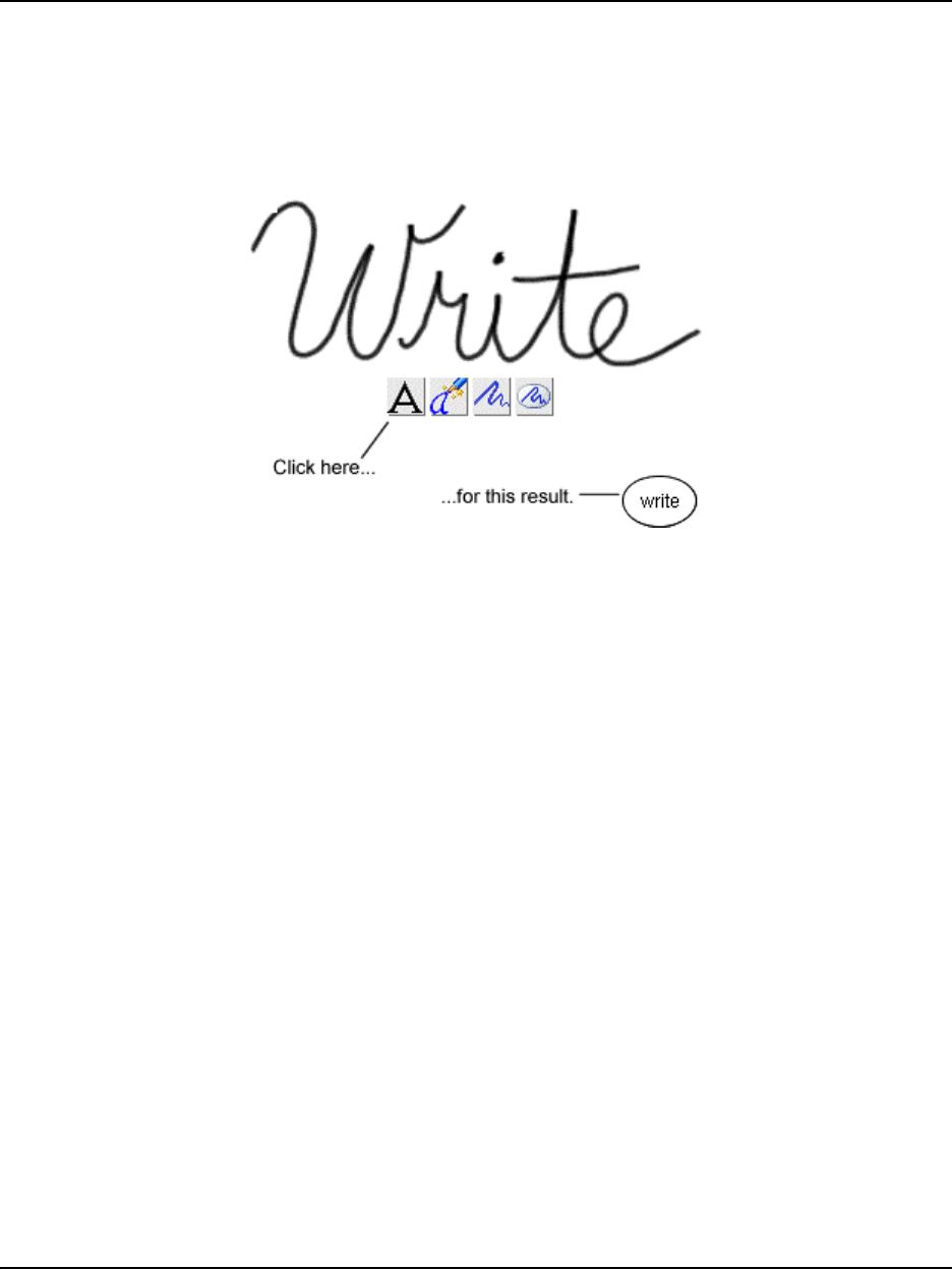
Using SMART Ideas Software on a SMART Board Interactive Whiteboard 93
Using SMART Ideas Software on a SMART Board
Interactive Whiteboard
Working on the SMART Board interactive whiteboard in your classroom is the best way to use
SMART Ideas software. Pick up a pen tray pen and write in the SMART Ideas workspace. Then
press a button to transform your handwritten annotation into typed text inside a symbol. This
makes it easy to quickly create symbols that contain clear, typed text—without having to dash over
to a keyboard.
Handwriting Recognition
The interactive whiteboard (when used with a projector) also provides an enlarged, bright image
that’s ideal for presenting diagrams to your class. With the touch-sensitive interactive whiteboard,
you can create and manipulate diagram objects right at the screen. Use your finger to move
symbols, add links, open sub-levels and activate toolbar buttons. Use a pen tray pen to create
symbols and connectors faster than you can with a keyboard or mouse. Then save everything that
you do at the interactive whiteboard into the current .ipr file.
To summarize, after creating a hand-drawn annotation on the SMART Board interactive
whiteboard with a pen tray pen, you can:
• transform it into a symbol with a typewritten label
• preserve it as a graphical symbol (if it’s a drawing)
• inject it (as converted typed text) into the next symbol or connector that you touch
• move it
• edit object labels in Outline view
• delete it
Creating Symbols with a Pen Tray Pen
For speed and ease of diagram creation, nothing beats working on a SMART Board interactive
whiteboard. Keep your keyboard and mouse out of the way: Use the Pen Tray pen to create
symbols (as described below), and then use your finger to change their appearance by activating
the buttons and menus of SMART Ideas software right at the screen.
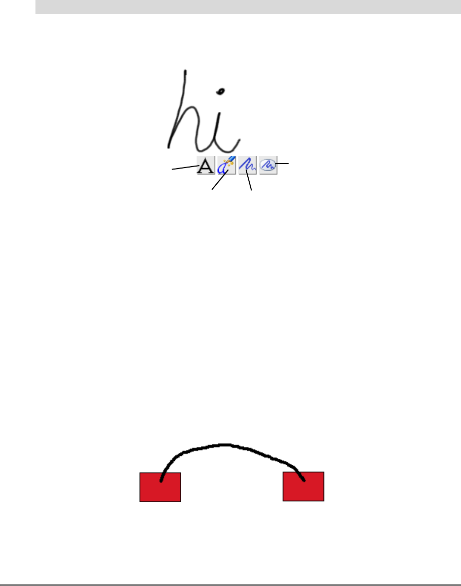
94 Using SMART Ideas Software on a SMART Board Interactive Whiteboard
You can convert your handwriting into conventional typewritten symbols or use it as is—a
handwritten graphical symbol.
NOTE: If your computer isn’t connected to an interactive whiteboard, select Tools > Pen, and then
you can then use your mouse to create handwritten annotations.
1. Pick up a pen from the pen tray, and then write in the SMART Ideas workspace.
Four buttons appear below your handwriting.
2. Without putting the pen back in the pen tray:
– Press the Convert to Typed Text button to convert your handwriting into typed text.
– Press the Inject Converted Text button to insert a typed version of your handwriting into
the next symbol or connector you touch.
– Press the Keep as Ink button to preserve your handwriting as a graphical object on its
own.
– Press the Keep as Ink inside a Symbol button to preserve your handwriting as a
graphical object inside a symbol.
Connecting Symbols with a Pen Tray Pen
The easiest and fastest way to connect two symbols is to pick up a pen tray pen and draw a line
from one symbol to the other. As long as the lines originate and end inside a symbol, SMART
Ideas software instantly transforms your roughly drawn line into a smoothly rendered line in the
current connector style, even copying the curvature of the line you drew. For example, pick up a
pen and draw a rough, curved line that starts inside one symbol and ends inside another.
SMART Ideas software replaces your rough line with a connector in the current style as soon as
you lift the pen from the screen.
You can even label the connector with the pen.
To create a typed symbol with a pen
Keep as ink Enclosed
in a symbol
Keep as Ink
Inject converted text into
next object touched
Convert to typed text
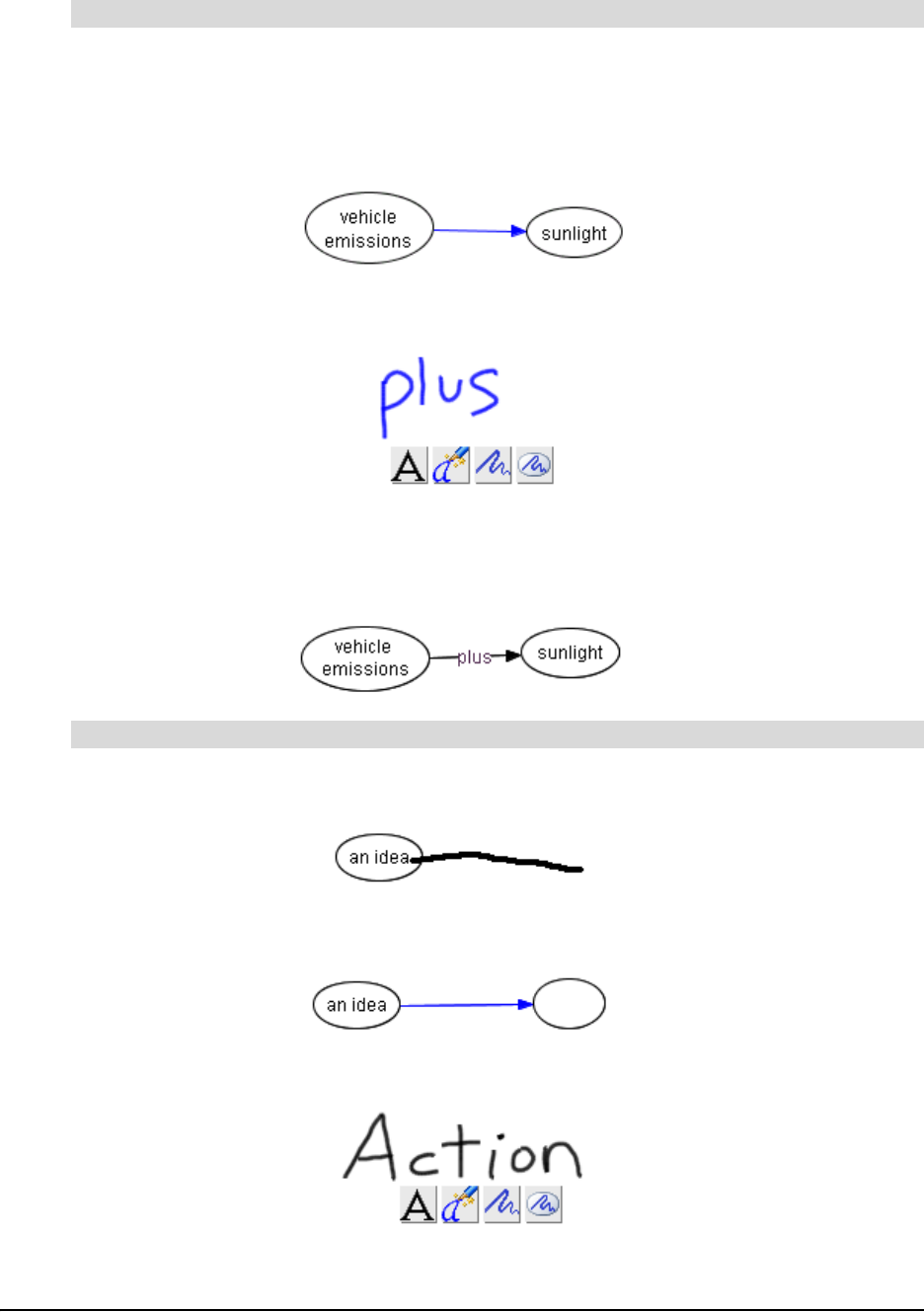
Using SMART Ideas Software on a SMART Board Interactive Whiteboard 95
1. Pick up a pen.
2. Draw a rough line from one symbol to another.
The line is converted into a straight line terminating in an arrowhead (unless you previously
chose another connector style).
3. Write some connector label text anywhere in the workspace.
4. Press the Inject Converted Text button.
5. With the pen, touch the connector that you want to label.
The connector displays the text label.
1. Draw a line emerging from any symbol.
A connected, blank symbol (in the current symbol style) appears at the end of the line.
2. Write a label for the blank symbol anywhere in the workspace.
3. Press the Inject Converted Text button.
To label a connector with a pen tray pen
To create a quickly connected (and labeled) diagram with a pen tray pen

96 Using SMART Ideas Software on a SMART Board Interactive Whiteboard
4. Touch the blank symbol with your pen.
The symbol displays the text label.
Editing with a Pen Tray Pen
Use a pen tray pen to edit the label for any symbol or connector in your diagram. While you can’t
selectively edit the letters or numbers inside a symbol or connector label, you can easily replace
the entire label using the Inject Converted Text button.
You also don’t need a keyboard to enter or edit text in the Outline view, and you can edit more
selectively than you can in the Diagram view. Pick up a pen, position the cursor where you want to
add or edit object text and then write in the text box.
1. Pick up a pen and write the replacement text anywhere in the SMART Ideas workspace.
2. Without putting the pen down, press the Inject Converted Text button.
3. Press the object (symbol, connector text or note) that contains the text that you want replaced.
Your handwritten text becomes the new text for the selected object.
To edit an object with a pen tray pen (in the Diagram or Outline view)
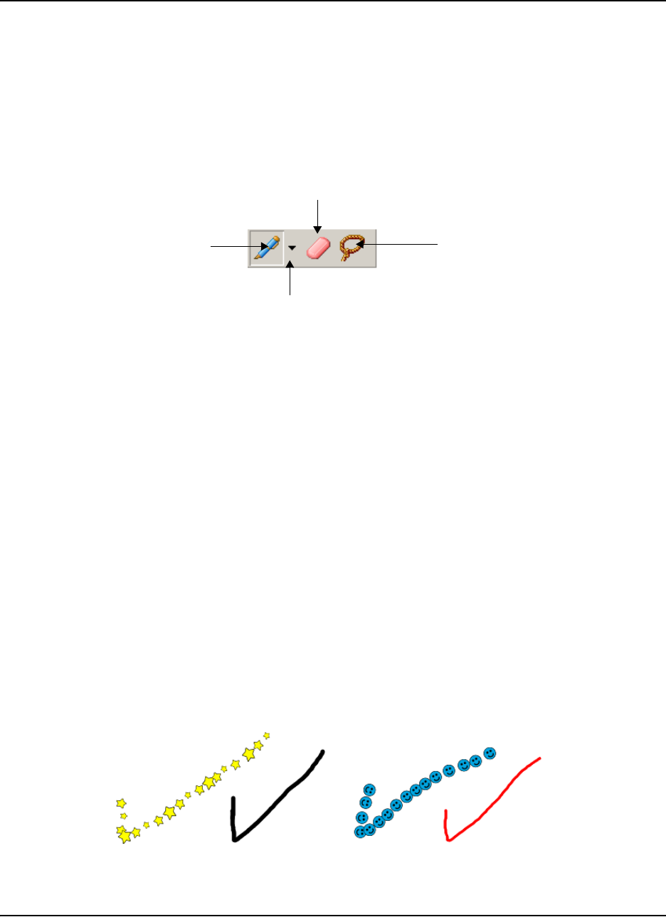
Using SMART Ideas Software on a Tablet PC 97
Using SMART Ideas Software on a Tablet PC
When used on a Tablet PC, SMART Ideas software does everything described in this guide —and
more. While this appendix focuses on those aspects of SMART Ideas software that have been
developed for Tablet PC owners, you should also read the other sections of this guide to become
familiar with all the features offered by this versatile concept-mapping software.
When you open SMART Ideas software on a Tablet PC, the Tablet Mode toolbar appears above
the center of the workspace. The Tablet Mode toolbar includes the Pen Tool button, Pen Settings
arrow, Eraser Tool button and Lasso Selection Tool button.
You use these buttons to create, edit and manipulate SMART Ideas objects with your tablet pen.
More specifically, you can use your tablet pen to:
• write or draw (page 97)
• create circle and square symbols (page 99)
• select objects (page 100)
• group and ungroup ink (page 101)
• connect symbols (page 102)
• erase objects (page 103)
NOTE: These buttons are also available to all other users of SMART Ideas software. Select Tools
> Customize to open the Customize dialog box. Select the Tablet Mode tab, and then select
Enable tablet mode.
Writing or Drawing using the Tablet Pen
Using your tablet pen, you can write and draw in the SMART Ideas workspace using ink of
different widths, colors and styles.
Pen Settings
Pen Tool
Lasso Selection
Tool
Eraser Tool
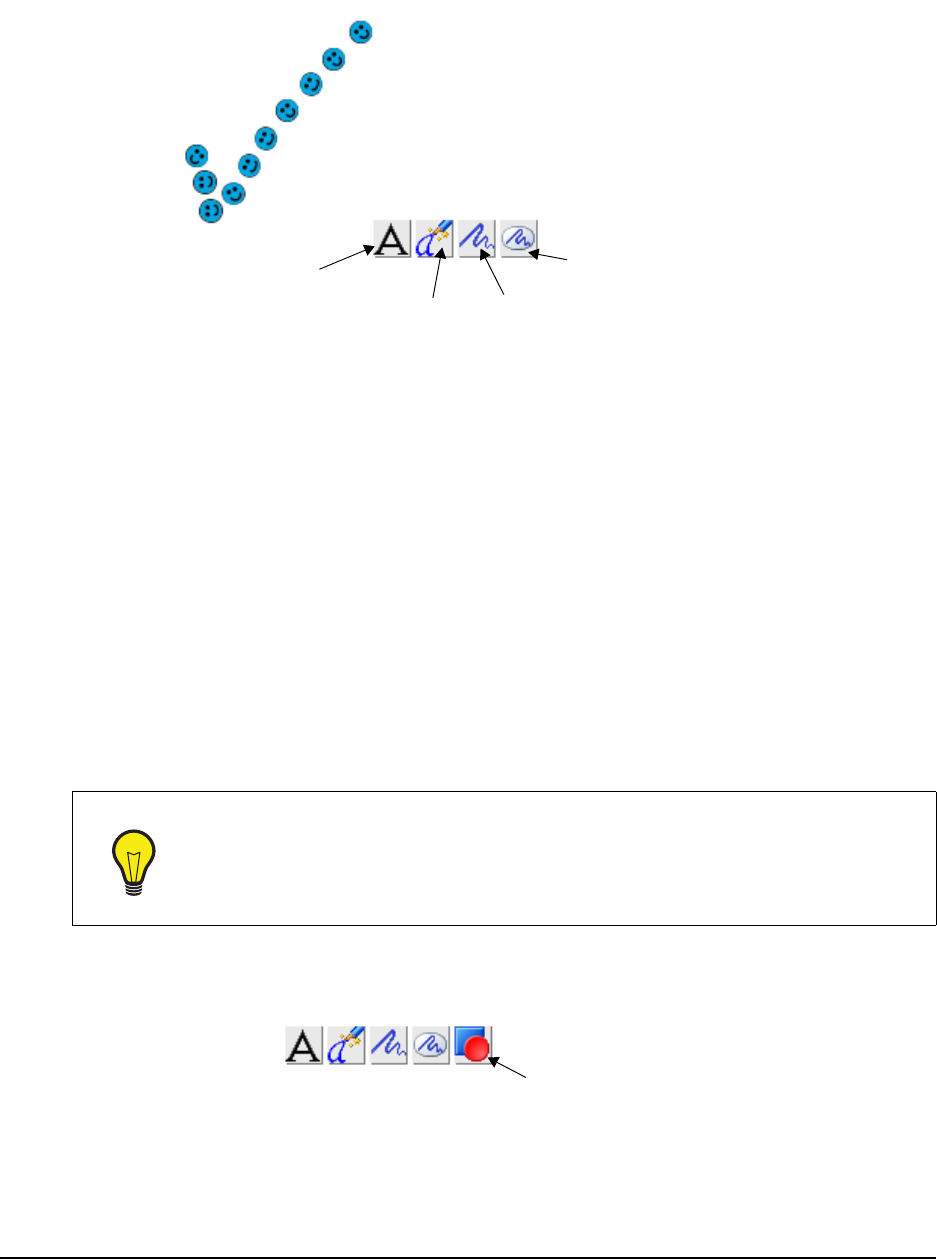
98 Appendix B: Using SMART Ideas Software on a Tablet PC
When you first write or draw with the tablet pen, four buttons appear next to the ink as soon as you
lift the pen from the workspace.
When you’re finished drawing or writing, tap any of the buttons to create an object that you can
change and manipulate. The function of these buttons is described below.
• Convert writing to typed text (inside a SMART Ideas symbol) by tapping the Convert to Text
button. A list of possible matches appears. You can either select the best match or the Try
Again option, which lets you rewrite and start the process again.
• Convert writing to typed text and then inject it into the next symbol you tap by tapping the
Convert and Inject button.
• Leave ink as a graphic object by tapping the Leave as Ink button.
• Leave ink as it is and put it inside a symbol with the Insert Ink into Symbol button.
However, instead of tapping any of these four buttons, you can also keep drawing or writing to
create a more elaborate drawing (or a longer handwritten note) made up of more pen strokes. The
four buttons remain displayed on the screen while you add additional pen strokes. When you’re
finished, tap one of the four buttons to convert all the pen strokes at once to a drawing or text
object.
In addition to the four buttons discussed above, a fifth button, called the Convert to Shape button,
appears when you draw a circle or a square with your tablet pen.
Tap the Convert to Shape button to transform a roughly drawn circle or square into a perfect
geometric symbol.
TIP
You must tap one of the three Ink buttons to complete a drawing or writing object. If
you don’t tap one of these buttons, everything you subsequently write or draw in
the workspace becomes a part of the original drawing, and your object may be
much larger than you’d intended. In other words, you may inadvertently create one
large object when you had intended to create several smaller objects.
Convert to Text
Leave as Ink
Convert and Inject
Convert Ink into Symbol
Convert to Shape
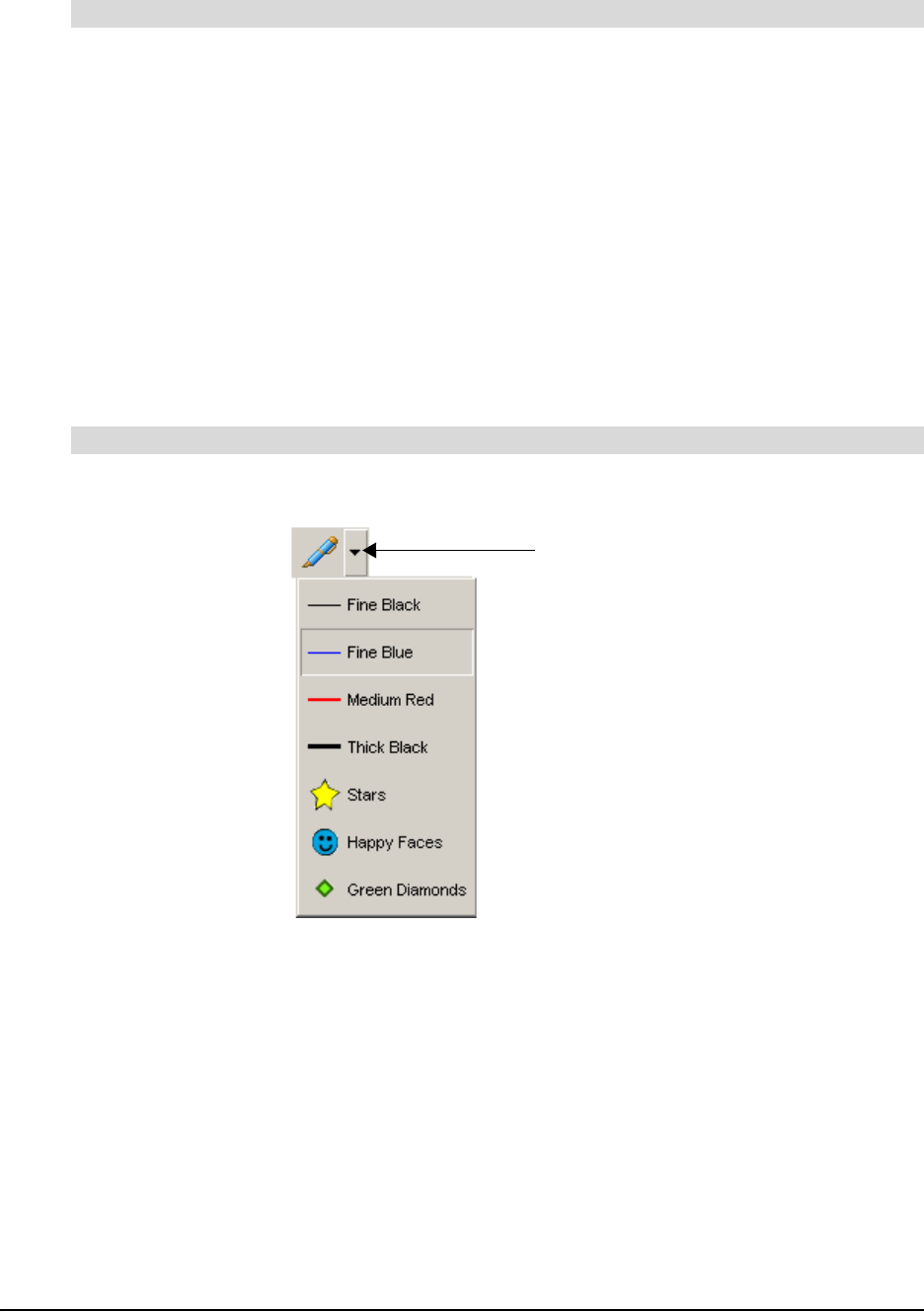
Appendix B: Using SMART Ideas Software on a Tablet PC 99
1. Use the tablet pen to write or draw in the SMART Ideas workspace. Ink appears in the
selected style.
When you lift the pen, four buttons appear beneath the ink.
2. Tap the Convert to Text button to convert the ink into typed text.
OR
Tap the Convert and Inject button to convert the ink into typed text and then inject it into the
next symbol or connector that you tap.
OR
Tap the Leave as Ink button to leave the ink as a graphic object.
OR
Tap the Insert Ink into Symbol button to put unconverted ink into a symbol.
1. With the tablet pen, tap the Pen Settings arrow button beside the Pen button.
2. Select an ink style from the list.
3. Write or draw in the workspace.
The ink appears in the selected style.
Create Circle and Square Symbols Using the Tablet Pen
When you draw a rough circle or square with your tablet pen, you can convert that drawing into a
symbol of the same size and color. This symbol behaves the same as any other SMART Ideas
symbol: You can connect it to other symbols, label it, create a sub-level beneath it, and change its
outline, shape and fill, etc.
To write or draw object
To change the appearance of ink
Pen Settings
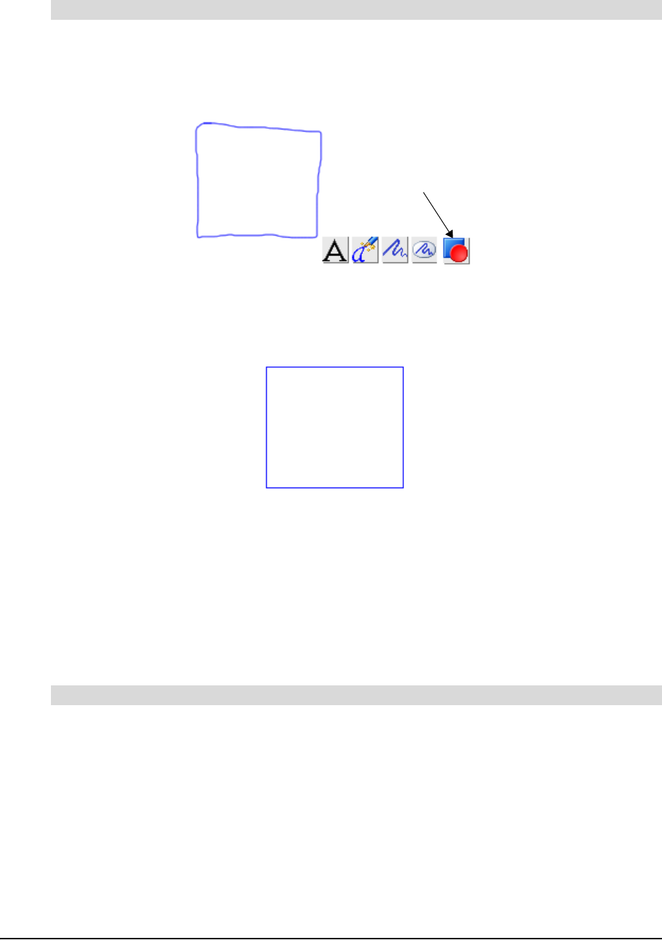
100 Appendix B: Using SMART Ideas Software on a Tablet PC
1. With the tablet pen, tap the Pen button.
2. Use the tablet pen to draw a circle or square in the SMART Ideas workspace.
When you lift the pen from the workspace, five buttons appear below the ink.
3. Tap the Convert to Shape button.
The roughly drawn rectangle changes to a perfect rectangle, the same color and size as the
original drawing.
You can now select the shape, and it behaves like any other SMART Ideas symbol.
Selecting Objects Using the Tablet Pen
You can select a single object by tapping the Lasso Selection button on the Tablet Mode toolbar,
and then either tap the object or roughly circle it with the tablet pen. However, the only way to
select several objects is to circle them with the pen. You don’t need to be precise when you use the
“lasso” selection technique: You need to surround only about sixty percent of the object or objects
to make your selection.
1. Tap the Lasso Selection button on the Tablet Mode toolbar.
2. Tap the object once with the tablet pen.
OR
Circle the object with the tablet pen.
To convert a drawing into a circular or square symbol
To select a single object
Convert to Shape

Appendix B: Using SMART Ideas Software on a Tablet PC 101
The object appears enclosed by a selection rectangle.
1. Tap the Lasso Selection button on the Tablet Mode toolbar.
2. Roughly encircle the objects you want to select.
NOTE: Only about sixty percent of the objects need to be encircled. In addition, you don’t
need to complete the circle for the selection to take place.
Grouping and Ungrouping Ink
When you finish a drawing and press the Leave as Ink button, each pen stroke in the drawing is
automatically grouped as a unit with all the other pen strokes. The pen strokes function as a unit,
and you can perform any action (such as resizing or changing line width or color) on the entire
group.
You can ungroup the object using the Ungroup Ink menu option, returning it to a collection of
individual pen-strokes. When you subsequently select the drawing, it appears as a cluster of
individually selected objects. You can then perform an action on only one pen stroke in the group.
You can also group drawings that you originally created as individual drawing objects using the
Group Ink menu option.
1. Tap the Lasso Selection button on the Tablet Mode toolbar.
2. Encircle the objects that you want to group into a single unit.
NOTE: You can’t include a symbol or connector in the group. This feature is strictly for writing
or drawing you’ve created with your tablet pen.
3. Select Tools > Group Ink.
The objects appear selected as a single unit.
TIP
Tapping an object to select it works best with symbols or connectors. It’s more
difficult to select unconverted ink drawing and writing in this manner because
you must be very careful to tap precisely on a drawing line (which can be quite
fine). For this reason, you should use the “lasso” selection technique and circle
drawing and writing objects with your pen.
To select several objects
To group pen strokes
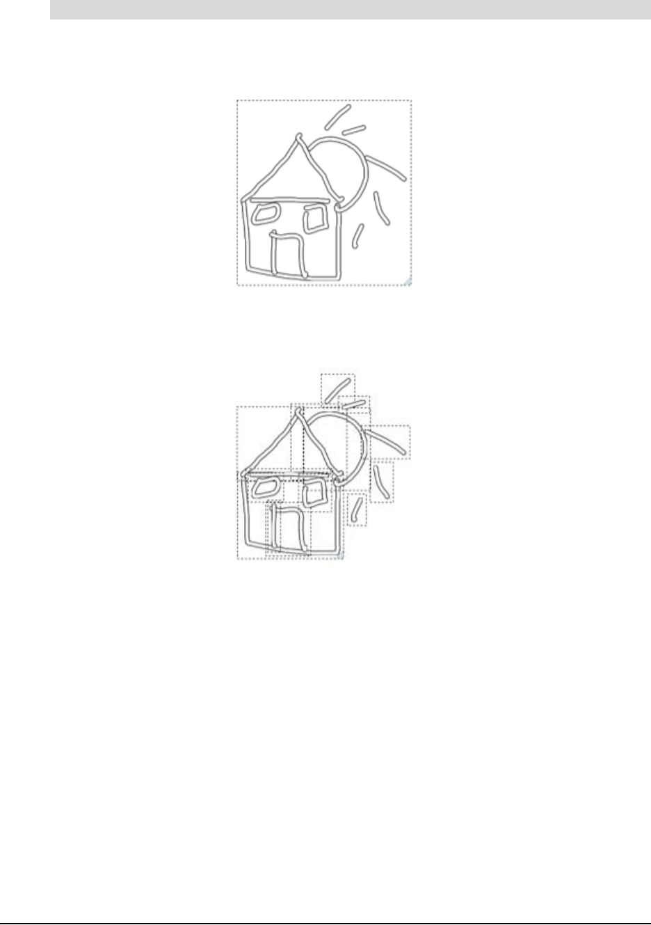
102 Appendix B: Using SMART Ideas Software on a Tablet PC
1. Tap the Lasso Selection button on the Tablet Mode toolbar.
2. Tap or encircle the drawing object you want to ungroup into its constituent pen strokes.
3. Select Tools > Ungroup Ink.
The object appears as a cluster of individually selected pen strokes.
Connecting Symbols with Your Tablet Pen
Use your tablet pen to draw a rough line from one symbol to another. As long as the line begins
inside one symbol and ends inside another, SMART Ideas software instantly transforms your
hand-drawn line into a smoothly rendered line in the current ink style, even copying the curvature
of the line you drew. You can use this method of connecting symbols to create an elaborate
concept map very quickly.
You can easily label connectors (and symbols, too) after you create them using the Convert and
Inject button.
To ungroup pen strokes

Appendix B: Using SMART Ideas Software on a Tablet PC 103
NOTE: The appearance of the connector is determined by the current ink style of the tablet pen.
For example, if the last selected ink style was the rubber duck motif, SMART Ideas software
replaces your hand-drawn line with a row of rubber ducks that terminates in an arrow head.
Erasing Objects with Your Tablet Pen
It’s easy to erase a symbol, connector or ink object using your tablet pen and the Eraser button on
the Tablet Mode toolbar. Tap the eraser button, and then tap a SMART Ideas symbol or connector
object to delete it. If the object is a symbol, any underlying sub-levels are deleted as well. Ink
drawing and writing, on the other hand, is erased pen stroke by pen stroke. This allows you to
erase the individual letters in a word, so you can correct spelling mistakes without rewriting the
entire word.
NOTE: You can also use the Delete button on the Standard toolbar to remove objects from the
workspace. However, when you use this button, you must first select the object you want to
remove. With the Eraser button, you don’t need to select the object before you erase it.

104 Appendix B: Using SMART Ideas Software on a Tablet PC

Customer Support 105
Customer Support
Online Support
Visit www.smarttech.com/support to view and download user’s guides, “how-to” and
troubleshooting articles, software and more.
Training
Visit www.smarttech.com/trainingcenter for training materials and information about our
training services.
Contacting SMART Technical Support
SMART Technical Support welcomes your call. However, if you experience difficulty with your
SMART product, you may want to contact your local reseller first. Your local reseller may be able
to resolve the issue without delay.
All SMART products include online, telephone, fax and e-mail support:
Online: www.smarttech.com/contactsupport
Telephone: +1.403.228.5940 or
Toll Free 1.866.518.6791 (Canada/U.S.)
(Monday to Friday, 5 a.m. – 6 p.m. Mountain Time)
Fax: +1.403.806.1256
E-mail: [email protected]
General Inquiries
Address: SMART Technologies
1207 – 11 Ave SW, Suite 300
Calgary, AB T3C 0M5
CANADA
Switchboard: +1.403.245.0333 or
Toll Free 1.888.42.SMART (Canada/U.S.)
Fax: +1.403.228.2500
E-mail: [email protected]
Registration
To help us serve you, register online at www.smarttech.com/registration.

106 Customer Support

Index 107
Index
A
Adding Legends 52
Adding Notes to Symbols 41
Adding Shadows to Symbols 43
Adding Sounds Files 39
Adding Styles to Style Collections 27
Adding Video Files 37
Aligning Symbols 15
B
Backgrounds 19, 60
C
Changing Connector Appearance 34
Changing Diagram Layouts 14
Changing Symbol Appearance 33
Checking the Spelling 68
Clip Art
Importing Images 46
Searching for 47
Symbols 45
Cliplets
Inserting 49
Introduction 48
Color Schemes 61
Concept Maps 1
Connecting Symbols 7
Connectors
Changing Appearance 34
Deleting 18
Formatting with Styles 24
Labeling 9
Linking Symbols 7
Selecting 11
Converting Style Collections 29
Copying Object Formats 36
Copying Objects 19
Creating Connected Diagrams 4
Creating Diagrams 3
Creating Layered Diagrams 71
Creating Links 74, 81
Creating Notes 81
Creating SMART Ideas Files 85
Creating Style Collections 26
Creating Sub-Levels 81
Creating Symbols 4
Creating Topics 80
Customizing Diagrams 33
Cutting Objects 19
D
Deleting Connectors 18
Deleting Symbols 18
Diagram View 57
Diagrams
Creating 4
Creating Layered Diagrams 71
Customizing 33
Editing 11
Navigating Layered Diagrams 74
Printing 88
Distributing Symbols 16
E
Editing Diagrams 11
Editing Text 67
Expanding Diagram Trees 65
Exporting SMART Ideas Files 86
F
Finding Text 69
Formatting Connectors with Styles 24
Formatting Symbols with Styles 21
Formatting Text 68
G
Global View 58
Gradients 35
Grid 60
Grouping Symbols 50
H
Hiding Toolbars 59
I
Importing Images 44
Importing Images as Clip Art 46

108 Index
Importing Style Collections 29
Inserting Cliplets 49
Interactive Cliplets 48
L
Labeling Connectors 9
Layered Diagrams
Creating 71
Navigating 74
Layouts 14
Legends 52
Linking Symbols with Connectors 7
Links
Creating 74, 81
Removing 77
Replacing 77
M
Maximizing the Workspace 59
Moving Symbols 12
N
Navigating the Sub-Levels 56
Navigating Through Layers 74
Notes
Adding to Symbols 41
Creating 81
O
Opening SMART Ideas Files 86
Outline View 57, 79
P
Pasting Objects 19
Present Mode 59
Printing Diagrams 88
Protecting Objects 19
R
Redoing Changes 20
Registering Your Slate 105
Removing Links 77
Replacing Links 77
Replacing Text 69
Resizing Symbols 17
Resizing Symbols to Show All Text 18
S
Saving SMART Ideas Files 86
Saving Style Collections 30
Searching for Clip Art 47
Selecting Connectors 11
Selecting Symbols 11
Shadows 43
Showing Sub-Levels 73
Shrinking Diagram Trees 65
Skins 63
SMART Board Interactive Whiteboards 93
SMART Ideas Files
Creating 85
Exporting 86
Opening 86
Saving 86
Sound Files 39
Spell-Checking 68
Style Collections
Adding Styles 27
Converting 29
Creating 26
Importing 29
Introduction 26
Saving 30
StylePaint 36
Styles
Adding to Style Collections 27
Formatting Connectors 24
Formatting Symbols 21
Introduction 21
Sub-Levels
Creating 81
Introduction 55
Navigating 56
Showing 73
Viewing 57

Index 109
Symbols
Adding Notes 41
Adding Shadows 43
Adding Sound Files 39
Adding Video Files 37
Aligning 15
Changing Appearance 33
Clip Art 45
Creating 4
Deleting 18
Distributing 16
Formatting with Styles 21
Grouping 50
Importing Images 44
Introduction 3
Moving 12
Resizing 17
Resizing to Show All Text 18
Selecting 11
Transparency 42
T
Tablet PC 97
Technical Support
Contacting 105
Templates 90
Text
Editing 67
Finding 69
Formatting 68
Replacing 69
Topics 80
Transparency 42
Two-Color Patterns 35
U
Undoing Changes 20
V
Video Files 37
Viewing Sub-Levels 57
Views
Diagram 57
Global 58
Outline 57, 79
Z
Zoom 64

110 Index

SMART Technologies
1207 - 11 Avenue SW, Suite 300
Calgary, AB T3C 0MS
CANADA
www.smarttech.com/support
www.smarttech.com/contactsupport
Email: support@smarttech.com
Support +1.403.228.5940 or Toll Free 1.866.518.6791
(Canada/U.S.)
Support fax + 1.403.806.1256
SPL 1021 - SMART ideas - User Gu4 4 10/3/2007 3:39:58 PM
