
827
FY 2011 Annual Progress Report
DOE Hydrogen and Fuel Cells Program
Jon P. Owejan (Primary Contact), Matthew Mench,
Michael Hickner, Satish Kandlikar, Thomas Trabold,
Jeffrey Gagliardo, Anusorn Kongkanand,
Wenbin Gu, Paul Nicotera
General Motors
10 Carriage Street
Honeoye Falls, NY 14472
Phone: (585) 953-5558
E-mail: [email protected]
DOE Managers
HQ: Donna Ho
Phone: (202) 586-8000
E-mail: [email protected]
GO: David Peterson
Phone: (720) 356-1747
E-mail: [email protected]
Technical Advisor
John Kopasz
Phone: (630) 252-7531
E-mail: [email protected]
Contract Number: DE-EE0000470
Subcontractors:
• PennStateUniversity,UniversityPark,PA
• UniversityofTennessee,Knoxville,TN
• RochesterInstituteofTechnology,Rochester,NY
Project Start Date: June 1, 2010
Project End Date: May 31, 2013
Fiscal Year (FY) 2011 Objectives
Characterize saturated relationships in state-of-the-art •
fuel cell materials.
Obtain a comprehensive down-the-channel validation •
data set for a baseline and auto-competitive material set.
Optimize component models to output bulk and •
interfacial transport resistances.
Demonstrate integrated transport resistances with a one •
plus one-dimension (1+1D) fuel cell model solved along
a straight gas flow path.
Identifycriticalparametersforlow-costmaterial•
development.
Technical Barriers
This project addresses the following technical barriers
from the Fuel Cells section of the Fuel Cell Technologies
ProgramMulti-YearResearch,Developmentand
Demonstration Plan:
(B) Cost
(C) Performance
(D) Water Transport within the Stack
Technical Targets
This project supports fundamental studies of fluid,
proton and electron transport with focus on saturated
operatingconditions.Insightsgainedfromthesestudies
are being used to develop modeling tools that capture
fundamental transport physics under single and two-phase
conditions.Thisprojectaddressestheexpectedoutcomes
from Topic 4a as follows:
Validated transport model including all component •
physical and chemical properties:
Down-the-channel pseudo-two-dimension (2D) –
model will be refined and validated with data
generated in the project.
Public dissemination of the model and instructions for •
exerciseofthemodel:
Project website to include all data, statistics, –
observations, model code and detailed instructions.
Compilation of the data generated in the course of •
model development and validation:
Reduceddatausedtoguidemodelphysicstobe –
published and described on project website.
Identicationofrate-limitingstepsand•
recommendations for improvements to the plate-to-
plate fuel cell package:
Model validation with baseline and auto- –
competitive material sets will provide key
performance limiting parameters.
FY 2011 Accomplishments
Generated distributed down-the-channel current, ohmic •
resistance, temperature and liquid water validation data
for a baseline material set.
Developed new characterization methods to measure •
transport relationships as a function of saturation.
Generated characterization data for bulk and interfacial •
transport in bulk membrane, thin ionomer films,
dispersed catalyst layers, gas diffusion layers and gas
delivery channels.
Developed wet model framework.•
V.F.4 Investigation of Micro- and Macro-Scale Transport Processes for Improved
Fuel Cell Performance

Owejan – General Motors
V.F Fuel Cells / Transport Studies
828
DOE Hydrogen and Fuel Cells Program
FY 2011 Annual Progress Report
Published validation and characterization data to a •
project website at: www.pemfcdata.org.
G G G G G
Introduction
The transport physics associated with fuel cell
operation is widely debated amongst researchers because
comprehensive micro/nano-scale process validation is
very difficult. Furthermore, fuel cell operation has a strong
interdependence between components making it difficult
to separate the key relationships required for predictive
modelswithexsitumethods.Generally,avalidatedmodel
that predicts operation based on known design parameters
for fuel cell hardware and materials is highly desired by
developers. Such a model has been proposed by many
research groups for dry (less than 100% relative humidity
[RH]exhaust)operationwithmoderatesuccess,however
these modelers unanimously assert that their ability to
predict wet operation is limited by two-phase component-
level understanding of transport processes. Additionally,
as two-phase models continue to be refined; benchmarking
progress is difficult due to incomplete validation datasets.
Inthecurrentwork,ourteamisdeveloping
characterization tools for saturated relationships based
on the evolution of a dry 1+1D model for accurate wet
prediction[1].Tocomplementthisworkwearealso
developing a comprehensive validation dataset based on
awideprotonexchangemembranefuelcell(PEMFC)
operating space. As data and modeling reach a final form,
these are uploaded to a project website at www.pemfcdata.
org. All characterization and validation work is conducted
with a common material set.
Approach
Thisprojectisorganizedaroundbaselineandnext-
generation material sets. These materials define parametric
bounds for component and integrated down-the-channel
modeling efforts. The baseline material set was chosen
basedonthecommercialstateoftheartthatexiststoday.
Thenext-generationmaterialsetconsistsoftransport
impacting parametric changes that are in-line with the DOE
2015 targets for reduced cost while improving durability
and performance. For characterization and validation
experiments,astandardprotocolwasalsodevelopedto
enabletheteamtoconductexperimentswiththesame
boundary conditions.
Therstphaseofthisprojectwasexperimentally
focused on characterization work that is organized by
transport domain, comprising thin film ionmers, bulk
membranes, porous electrodes, gas diffusion layers and
flow distribution channels. More specifically, the key
relationships being investigated are outlined as follows:
IonomerCharacterization•
Membrane water uptake, water diffusivity and –
hydraulic permeability.
Oxygenandwatertransportasafunctionof –
ionomer layer thickness.
Evidence of nanophase/water morphological –
changes vs. film thickness.
Diffusion Layer Characterization •
Microporous layer thermal conductivity and D/D –
eff
as a function of saturation.
Catalyst layer liquid water pressure as a function of –
saturation, pore size, and hydrophobicity.
Substrate thermal conductivity (wet and dry) and –
D/D
eff
as a function of saturation.
Through-plane saturation and wet region boundary –
as a function of dT and operating temperature.
Channel Characterization •
Carbon fiber paper (CFP) to channel interfacial –
transport resistance as a function of channel
saturation.
Channel dP as a function of saturation, –
temperature, flow, and current density.
Manifold dP as a function of saturation, –
temperature, and flow.
These relationships are required to develop component
models that output bulk and interfacial transport resistances
totheproject1+1Ddown-the-channelmodel.Inanticipation
of this integrated model, a validation data set is being
collected in parallel with small scale hardware specifically
designedtoincludeautomotivestackconstraints[2].
Results
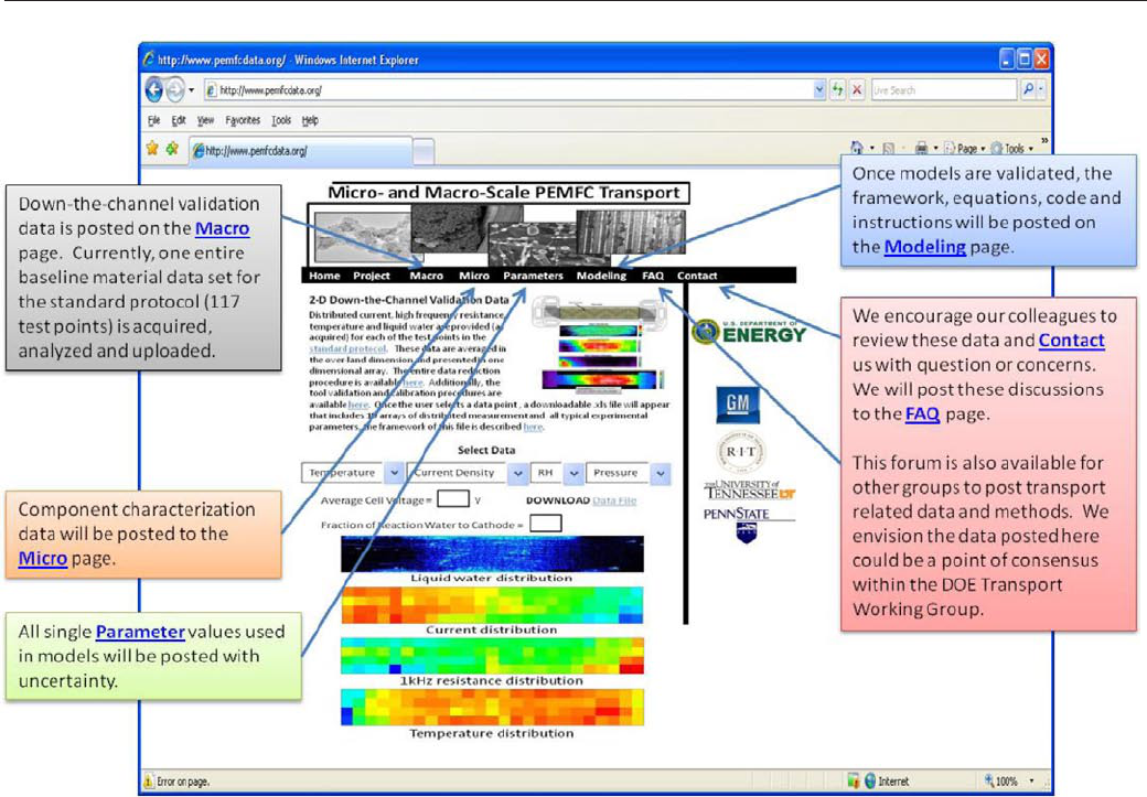
Project Website
The project website was made available to the public at
www.pemfcdata.org. This information tool is designed for
sharing project data and modeling with the broader fuel cell
research community to provide a common validation tool
that generates dialog about fundamental transport physics in
PEMFCs. A navigational map of the current website is given
in Figure 1.
This website contains a ‘Home’ and ‘Project’ page
that describes the funding, participants, news, approach,
deliverables, standard materials and testing protocol. The
‘Macro’ page contains the down-the-channel validation
dataforthebaselinematerialsetandthenext-generation
materialsetwillbeuploadedinthenextphaseofthe
project. The ‘Micro’ page is continuously being updated
with characterization data as it becomes available. The list
of model parameters is posted to the ‘Parameters’ page. This
list is currently posted for the dry-based model only, which is
available on the ‘Modeling’ page (the wet model is currently
being developed and will be posted in the second phase
829
FY 2011 Annual Progress Report
DOE Hydrogen and Fuel Cells Program
V.F Fuel Cells / Transport Studies
Owejan – General Motors
of the project). Finally, the ‘Contact’ and ‘FAQ’ pages are
intended to initiate dialog regarding our data and approach.
Baseline Validation Data
Experimentalvariabilitywascarefullyexaminedprior
to collecting the baseline material set data for the 117
point standard protocol. With regard to the controlled test
parameters, temperature control with cartridge heaters was
found to have the most significant impact on test variation.
RHuctuationswithinthecellresultfromtemperature
variations as heaters cycle, and this impacts all aspects of
transport within the cell. Liquid coolant with flow and
temperaturecontrolwasusedtomitigatethisexperimental
variability, which was confirmed with our temperature
distribution tool by comparing the temperature distributions
with and without coolant. This comparison showed
a constant temperature profile is achieved with liquid
coolant. Moreover, the temperature distribution is more
representative of a commercial fuel cell system with coolant,
as the temperature gradient should increase toward the
coolant outlet side. For this reason, most 50 cm
2
validation
experimentswillutilizeliquidcoolantduringthecourseof
the project.
The validation data set includes distributed liquid
water, current, high frequency resistance and temperature
measured across the active area. Additionally, anode vs.
cathode water balance based on condensed outlet water was
collected for each test point. A tool (shown in Figure 1) was
developed to navigate this database such that our team and
other interested researchers can select a test point from the
standard protocol to download the raw and processed data.
Currently the validation dataset is fully populated for the
baseline material set.
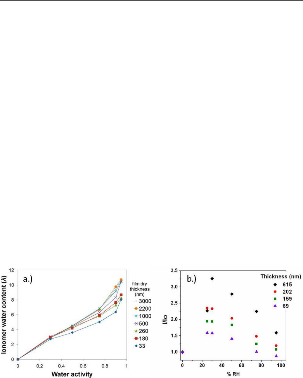
Transport in Thin Ionomer Films
Ellipsometric, microbalance, and fluorescence
measurements on thin Nafion
®
films have been performed
on model surfaces. These characterization techniques on
ionomer films with thicknesses between 30 and 600 nm are
designed to probe the transport and swelling properties of
the thin ionomer films in the catalyst layers. Ellipsometry
and microbalance measurements can give us highly accurate
measurements of the water content and swelling of these
lmsasafunctionofRH.Theuorescencemeasurements
shed light on the dynamics of the film, which governs the
Figure 1. Project Website Navigational Map
Owejan – General Motors
V.F Fuel Cells / Transport Studies
830
DOE Hydrogen and Fuel Cells Program
FY 2011 Annual Progress Report
water self-diffusion and transport properties. Fluorescence
measurements probe the dynamics in the aqueous domains
and we have also used grazing incidence small-angle X-ray
scattering to probe their structure. Both the water uptake or
hydration number (λ) and self-diffusion of water within the
lmdeterminesitsoxygenandprotontransportproperties
as these species move through the aqueous domains of
the material. Select microbalance and fluorescence are
presented herein to demonstrate the sensitivities being
observed in thin films.
Microbalance results shown in Figure 2a indicate that
water content for different film thicknesses was similar for
Nafion
®
lmsongoldthickerthan500nm[3].Atlower
thicknesses, slightly lower water contents were observed,
especially at high vapor water activities. The origin of
the observed depression in water content is still unclear.
InteractionoftheionomerwiththeAusubstratecould
constrain the film from swelling, which is essential for water
sorption.Itisalsoconceivablethatawaterimpermeable
layer (disordering of water channels) at the gas/ionomer
interface may contribute to the observation. Fluorescence
intensitymeasurementsof9-([E]-2-carboxy-2-cyanovinyl)
julolidine (CCVJ) in thin Nafion
®
films given in Figure
2b show that the fluorescence response is a function of
thickness.HigherI/Ioresponseindicatesstiffeningof
the film upon water uptake which is not observed for the
membrane,buthasbeenreportedforotherthinlms[4].
Since the CCVJ fluorescence signal is controlled by the
local viscosity or mobility of the sample, it can be used to
measurewaterdiffusioninpolymers[5].TheI/Iosignal
will be related to the self-diffusion coefficient of water in
thenextphaseofthiswork.Thesemeasurementsindicate
different water dynamics in thin and thick films and provide
fundamental information on potential differences in proton
conductivity and other transport properties as a function of
film thickness.
Transport in Diffusion Materials
Severalinsituandexsitumeasurementsarebeing
used to measure transport in the porous components that
include the electrode, microporous layer and carbon fiber
macroporoussubstrate.Insituneutronimaging,infrared
imaging and acoustic microscopy are being used to map
through-plane liquid water distributions within the anode
vs.cathodediffusionlayers.Exsituworkisfocusedon
thermal conductivity and mass diffusivity as a function of
water saturation, and capillary pressure relationships for the
baseline diffusion media and catalyst layer are underway.
Uniquetestcellsandmethodologycapableofcontrolling
saturation have been developed to complete this testing.
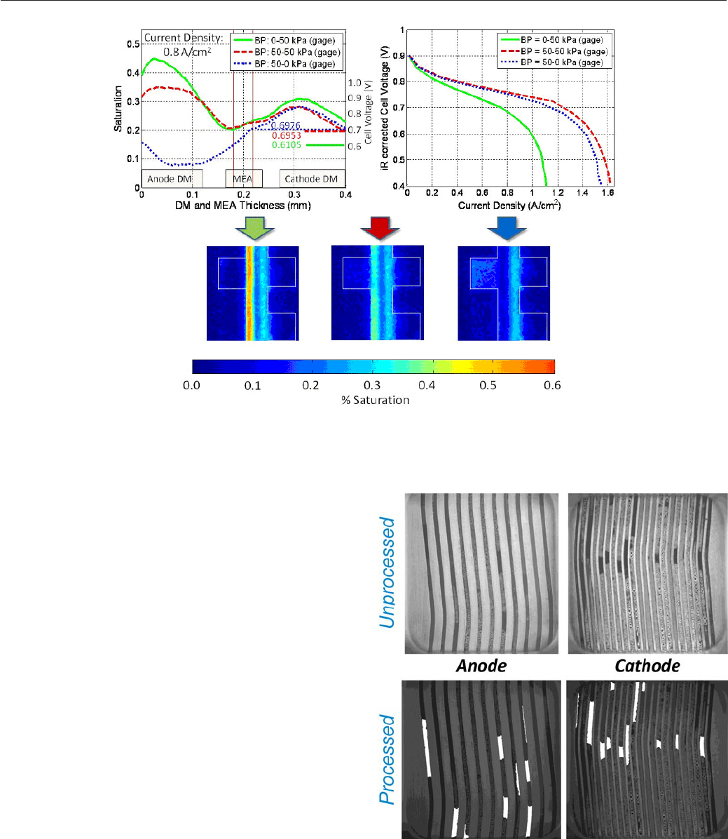
One characteristic result from the standard protocol
has been selected for presentation in this paper and the
complete reduced data set has also been made public at the
website. Measured with high resolution neutron imaging,
Figure 3a shows the effect of anode vs. cathode outlet
pressure differentials on water saturation. The operating
temperature is 40
0
C,anode/cathodeRHis95/95%andthe
current density is 0.8 A/cm
2
.Itisevidentfromtheplothow
the higher pressure on the cathode side shifts the saturation
towards the anode and vice versa. These data provide
insightintothecomplexwaterbalancetobemodeled.The
corresponding voltages have also been recorded in the
plot. Polarization curves obtained with fast scans after each
operating condition (Figure 3b) demonstrate the effect of the
pressure differential on performance. The false color images
in Figure 3c show the regions of water accumulation relative
to the land/channel geometry for the specific operating
conditions. These data also indicate how sensitive anode gas
diffusion layer (GDL) saturation is, and this is not typically
considered in two-phase models to this point.
Figure 2. Water interaction with varying thicknesses of thin Nafion
®
films as a function of water activity: a) water uptake at 80°C, b) CCVJ fluorescence
response at 25°C.
831
FY 2011 Annual Progress Report
DOE Hydrogen and Fuel Cells Program
V.F Fuel Cells / Transport Studies
Owejan – General Motors
Transport in Flow Distributor Channels
Two key components of the down-the-channel model
are the relationships between channel water saturation
and both CFP to channel interfacial transport resistances,
and the channel pressure drop. Therefore, it is critical to
establish a well-defined channel water saturation metric. A
technique has been developed to quantify the in situ channel
water saturation through the combined utilization of high
speed videos of the flow field channels during operation and
digitalimageprocessing[6].Theimageprocessingalgorithm
automatically detects static and dynamic liquid water, and
also characterizes the flow structure of each water object.
The water coverage ratio parameter along with channel
pressure drop as a function of saturation are providing
crucial information pertaining to transport resistance
associated with liquid water accumulation in the flow field
channels. Sample images showing pre- and post-processed
flow field channels and the resulting water detection are
showninFigure4.Inadditiontothischaracterizationof
wateradjacenttotheCFPintheactivearea,experiments
are underway to characterize the resistance of liquid water
transitioning from the bipolar plate micro-channels in the
gas manifolds of a fuel cell stack. Here the combination
of low gas shear and contact line pinning has been found
to cause water stagnation at the plate edge. This results
in additional plate-to-plate flow variations that must be
captured in a true two-phase fuel cell model.
Figure 3. Impact of varied outlet pressure: a) GDL water saturation and through-plane, b) polarization curves,
c) false color images showing saturation.
Figure 4. Representative unprocessed and processed high speed images
of liquid water distribution in both anode and cathode channels. The
processed images can provide quantified information of local and overall
water coverage ratio.

Owejan – General Motors
V.F Fuel Cells / Transport Studies
832
DOE Hydrogen and Fuel Cells Program
FY 2011 Annual Progress Report
FY 2011 Publications/Presentations
1.J.Gagliardo,J.Fagley,D.Fultz,J.Owejan,“Inuence
of Through-Plane Thermal Profile on Water Accumulation
inProtonExchangeMembraneFuelCells”Meetingofthe
Electochemical Society, Las Vegas, NV. October 2010.
2. Jacob M LaManna, Fengyuan Zhang, Subhadeep
Chakraborty, and Matthew M. Mench, Quantification of
Through-Plane Liquid Water Gradients and Transport in
PEFCswithHighResolutionNeutronImaging.Acceptedfor
Presentation, 2011 ECS Meeting, Montreal Canada.
3.
ZijieLu,CodyRath,GuangshengZhang,
Satish G. Kandlikar. Water management studies in PEM fuel
cells,partIV:Effectsofchannelsurfacewettability,geometry
and orientation on the two-phase flow in parallel gas channels,
InternationalJournalofHydrogenEnergy(2011).
4.Kongkanand,A.,“InterfacialWaterTransportMeasurements
inNaonThinFilmsUsingaQuartz-CrystalMicrobalance,”
J. Phys. Chem. C, 115, pp. 11318-11325, (2011).
5. Sergi, J.M., Kandlikar, S.G., “Quantification and
Characterization of Water Coverage in PEMFC Gas Channels
UsingSimultaneousAnodeandCathodeVisualizationand
ImageProcessing,”InternationalJournalofHydrogenEnergy,
Accepted Manuscript, 2011.
6.
J.Owejan,DOEAnnualMeritReview,ArlingtonVA,May
12, 2011.
References
1.Gu,W.,Baker,D.R.,Liu,Y.,Gasteiger,H.A., “Proton
exchangemembranefuelcell(PEMFC)down-the-channel
performancemodel,”Handbook of Fuel Cells - Volume 5, Prof.
Dr. W. Vielstich et al. (Eds.), John Wiley & Sons Ltd., (2009).
2. Owejan, J.P., Gagliardo, J.J., Sergi, J.M., Kandlikar, S.G.,
Trabold, T.A., “Water management studies in PEM fuel
cells,PartI:Fuelcelldesignandinsituwaterdistributions,”
InternationalJournalofHydrogenEnergy,34(8),pp.3436-
3444, (2009).
3.
Kongkanand,A.,“InterfacialWaterTransportMeasurements
inNaonThinFilmsUsingaQuartz-CrystalMicrobalance,”
J. Phys. Chem. C, 115, pp. 11318-11325, (2011).
4.Nolte,A.J.;Treat,N.D.;Cohen,R.E.;Rubner,M.F.
Macromolecules, 41, 5793–5798, (2008).
5.
Miller,K.E.;Krueger,R.H.;Torkelson,J.M.,J.Polym.Sci.:
Polym. Phys, 33, 2343-2349, (1995).
6. Sergi, J.M., Kandlikar, S.G., “Quantification and
Characterization of Water Coverage in PEMFC Gas Channels
UsingSimultaneousAnodeandCathodeVisualizationand
ImageProcessing,”InternationalJournalofHydrogenEnergy,
Accepted Manuscript, 2011.
To optimize the channel design for better water
management, the effects of channel surface wettability,
cross-sectional geometry and orientation on the two-phase
owinparallelgaschannelswereinvestigated.Itwasfound
that hydrophilic channels are advantageous over uncoated
or slightly hydrophobic channels in terms of uniform water
and gas flow distribution and promoting film flow. Stamped
metal geometry channels favor film flow when compared
to a rectangular geometry. Vertical channel orientation is
advantageous over horizontal orientation because it is less
prone to slug flow, and facilitates more uniform liquid water
distribution and stable operation.
Conclusions and Future Directions
A well organized characterization, modeling and
validation framework was developed early in this project.
Therstphaseofexecutionwaslargelyfocusedon
experimentaldevelopmentwithkeyaccomplishments
outlined as follows:
Project is standardized by materials and operating space:•
Baseline and auto-competitive material sets chosen
–
based on parametric variations that consider
degradation and cost vs. performance trade-offs.
Key relationships required for a wet 1+1D model and •
characterization methods are defined:
Subjectmatterexpertsaredevelopingandexecuting –
characterization methods to generate physical
understanding of fundamental processes.
Component models describing processes are being
–
generated and will be used to output bulk and
interfacial transport resistances.
Modeling framework for 1+1D model is defined.
–
Down-the-channel baseline material validation data set •
complete:
Additionalrepeatexperimentsbeingexecutedto –
define uncertainty.
Database on the website for dissemination of data and •
modeling:
Visit www.pemfcdata.org (development will
–
continue throughout the project).
Thenextphaseofthisprojectisfocusedonrening
the component and down-the-channel models in parallel
while repeating characterization and validation work for the
next-generationmaterialset.Thisworkwillsupportthekey
deliverablefornextyear:avalidated1+1Dmodelcapableof
predicting performance and water balance under saturated
conditions with baseline material parameters.
